!J
\\
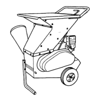
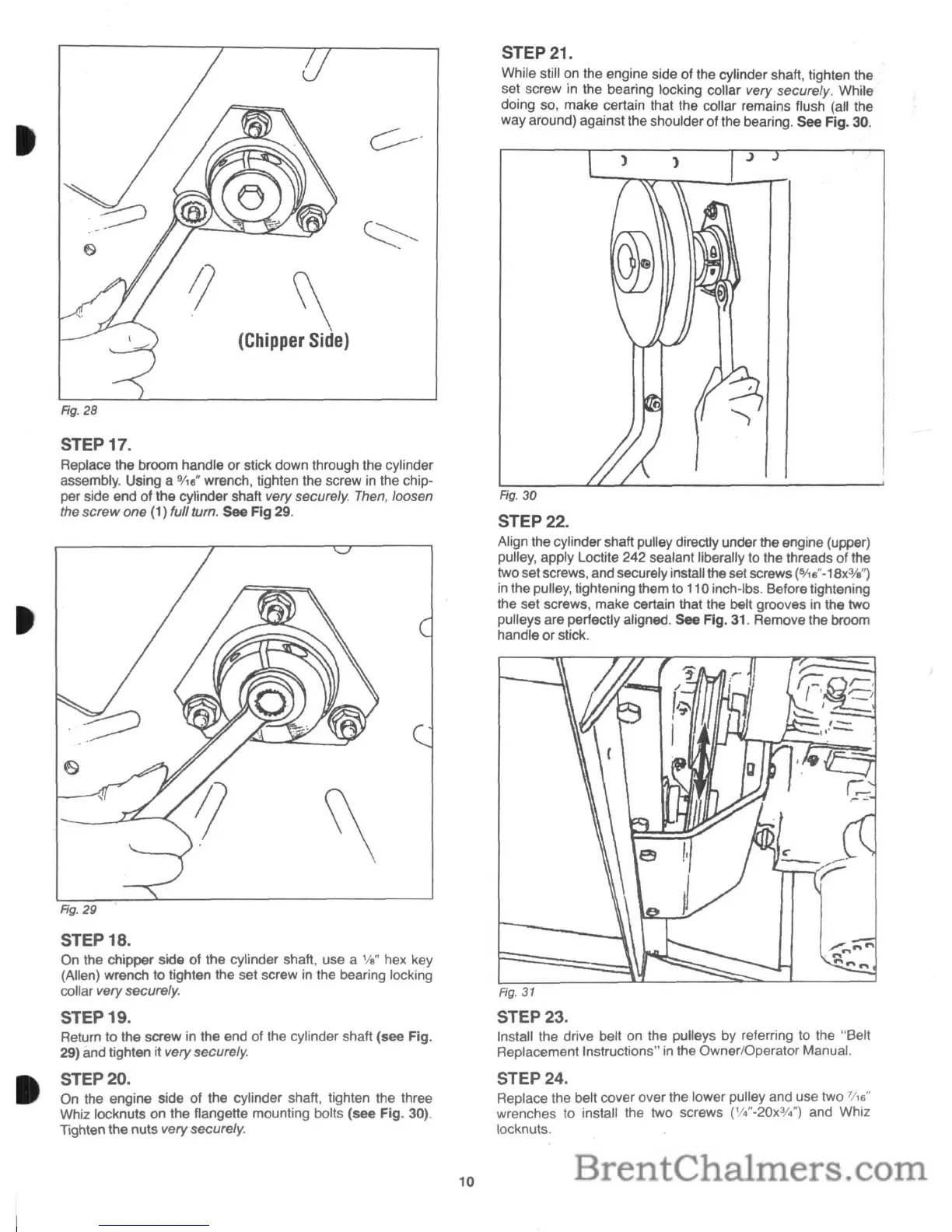
(Chipper
Side)
Fig.
28
STEP 17.
Replace the broom handle
or
stick down through the cylinder
assembly. Using a
9/
16
" wrench, tighten the screw
in
the chip-
per side end
of
the cylinder shaft very securely.
Then,
loosen
the
screw
one (1) full turn. See
Fig
29.
Fig.
29
STEP 18.
On
the chipper side
of
the cylinder shaft, use a
1Je"
hex key
(Allen) wrench to tighten the set screw
in
the bearing locking
collar
very securely.
STEP 19.
Return to the screw
in
the end of the cylinder shaft (see Fig.
29) and tighten it
very securely.
STEP 20.
On the engine side of the cylinder shaft, tighten the three
Whiz locknuts on the flangette mounting bolts (see Fig. 30).
Tighten the nuts
very securely.
10
STEP 21.
While still on the engine side of the cylinder shaft, tighten the
set screw
in
the bearing locking collar very securely. While
doing so, make certain that the collar remains flush (all the
way around) against the shoulder of the bearing. See Fig.
30.
STEP 22.
Align the cylinder shaft pulley directly under the engine (upper)
pulley, apply Loctite 242 sealant liberally to the threads
of
the
two set screws, and securely install the set screws
(5/
16
"-18x%")
in
the pulley, tightening them to 110 inch-Ibs. Before tightening
the set screws, make certain that the belt grooves
in
the two
pulleys are perfectly aligned.
See
Fig. 31. Remove the broom
handle or stick.
STEP 23.
Install the drive belt on the pUlleys by referring to the "Belt
Replacement Instructions"
in
the Owner/Operator Manual.
STEP 24.
Replace the belt cover over the lower pulley and use two
7/
16
"
wrenches to install the two screws ('I4"-20x%") and Whiz
locknuts.
 Loading...