Assembly & Set-Up
3
9
Tractor Set-Up
Connecting the Battery Cables
CALIFORNIA PROPOSITION 65 WARNING:
Battery posts, terminals, and related accessories
contain lead and lead compounds, chemicals known
to the State of California to cause cancer and
reproductive harm. Wash hands after handling.
CAUTION: When attaching battery cables, always
connect the POSITIVE (Red) wire to its terminal first,
followed by the NEGATIVE (Black) wire.
For shipping reasons, both battery cables on your equipment
may have been left disconnected from the terminals at the
factory. To connect the battery cables, proceed as follows:
NOTE: The positive battery terminal is marked Pos. (+). The
negative battery terminal is marked Neg. (–).
1. Remove the plastic cover, if present, from the positive
battery terminal and attach the red cable to the positive
battery terminal (+) with the bolt and hex nut. See Figure 3-1.
2. Remove the plastic cover, if present, from the negative
battery terminal and attach the black cable to the negative
battery terminal (–) with the bolt and hex nut. See Figure 3-1.
Figure 3-1
3. Position the red rubber boot over the positive battery
terminal to help protect it from corrosion.
NOTE: If the battery is put into service after the date shown
on top/side of battery, charge the battery as instructed in the
Maintenance section your Operator’s Manual prior to operating
the tractor.
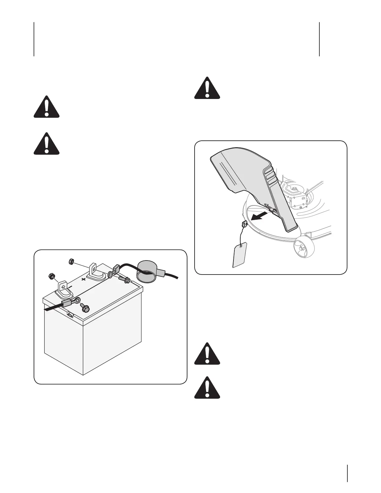
Shipping Brace Removal
WARNING! Make sure the riding mower’s engine is
off, remove the ignition key, and set the parking
brake before removing the shipping brace. Refer to
the Controls and Features section for instructions on
how to set the parking brake.
• Locate the shipping brace, if present, and accompanying
warning tag found on the right side of the mower, between
the discharge chute and the cutting deck. See Figure 3-2.
Figure 3-2
• Place the deck lift lever in the highest cutting position.
Refer to Setting the Cutting Height in the Operation
section of this manual.
• While pushing the discharge chute towards the machine
with your left hand, remove the shipping brace with your
right hand by grasping it between your thumb and index
finger and rotating it clockwise.
WARNING! The shipping brace, used for
packaging purposes only, must be removed and
discarded before operating your riding mower.
WARNING! The mowing deck is capable of
throwing objects. Failure to operate the riding
mower without the discharge cover in the proper
operating position could result in serious personal
injury and/or property damage.
Assembly & Set-Up
3
9