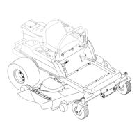
Section3: FeaturesandControls
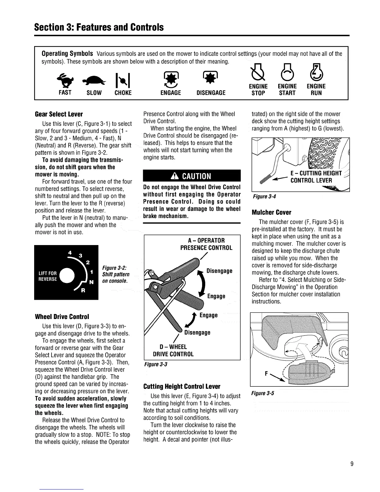
Operating Symbols Varioussymbolsare usedon the mowerto indicatecontrol settings (your modelmay not haveall of the
symbols).Thesesymbolsareshown below with a descriptionof their meaning.
ENGINE ENGINE ENGINE
FAST SLOW CHOKE ENGAGE DISENGAGE STOP START RUN
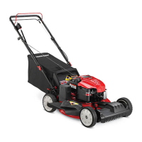
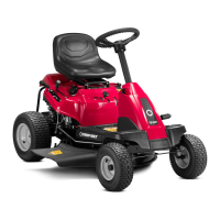
Gear Select Lever
Usethis lever (C,Figure3-1) to select
anyof four forward groundspeeds(1 -
Slow,2 and3 - Medium,4 - Fast),N
(Neutral)and R(Reverse).The gearshift
patternisshown in Figure3-2.
Toavoiddamagingthetransmis-
sion, donotshiftgearswhenthe
mowerismoving.
Forforward travel, use oneof thefour
numberedsettings.To select reverse,
shift to neutralandthen pull upon the
lever.Turnthe leverto the R (reverse)
positionand releasethe lever.
Putthe leverin N(neutral)to manu-
ally pushthe mowerand whenthe
moweris not in use.
PresenceControlalong with the Wheel
DriveControl.
Whenstartingthe engine,theWheel
DriveControlshould bedisengaged(re-
leased).This helpsto ensurethat the
wheelswill not startturning whenthe
enginestarts.
Do notengagetheWheel DriveControl
without first engaging the Operator
Presence Control. Doing so could
resultin wear or damageto the wheel
brakemechanism.
Figure3-2:
Shiftpattern
onconsole.
A- OPERATOR
PRESENCECONTROL
Disengage
Engage
Wheel Drive Control
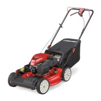
Usethis lever (D, Figure3-3) to en-
gageanddisengagedrive to thewheels.
Toengagethe wheels,first selecta
forward or reversegearwith the Gear
SelectLeverandsqueezethe Operator
PresenceControl(A,Figure3-3). Then,
squeezetheWheel DriveControllever
(D)againstthe handlebargrip. The
ground speedcanbevariedby increas-
ing or decreasingpressureon the lever.
Toavoidsuddenacceleration,slowly
squeezetheleverwhenfirstengaging
thewheels.
Releasethe WheelDriveControlto
disengagethe wheels.Thewheelswill
graduallyslow to a stop. NOTE:Tostop
the wheelsquickly, releasethe Operator
J Engage
Disengage
D- WHEEL
DRIVECONTROL
Figure3-3
Cutting Height Control Lever
Usethis lever (E,Figure3-4) to adjust
thecutting heightfrom 1to 4 inches.
Notethat actualcutting heightswill vary
accordingto soil conditions.
Turnthe leverclockwiseto raisethe
heightor counterclockwiseto lowerthe
height. A decalandpointer (not illus-
trated) onthe right sideofthe mower
deckshow the cutting heightsettings
rangingfrom A (highest)to G (lowest).
Figure3-4
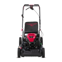
Mulcher Cover
Themulchercover (F,Figure3-5) is
pre-installedatthe factory. It must be
kept in placewhen using theunit as a
mulchingmower. The mulchercoveris
designedto keepthe dischargechute
raisedupwhileyou mow. Whenthe
cover isremovedfor side-discharge
mowing,the dischargechutelowers.
Referto "4. SelectMulching or Side-
DischargeMowing" in the Operation
Sectionfor mulchercoverinstallation
instructions.
Figure3-5
 Loading...