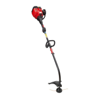
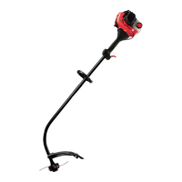
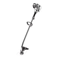
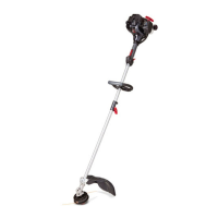
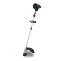
ASSEMBLY
6
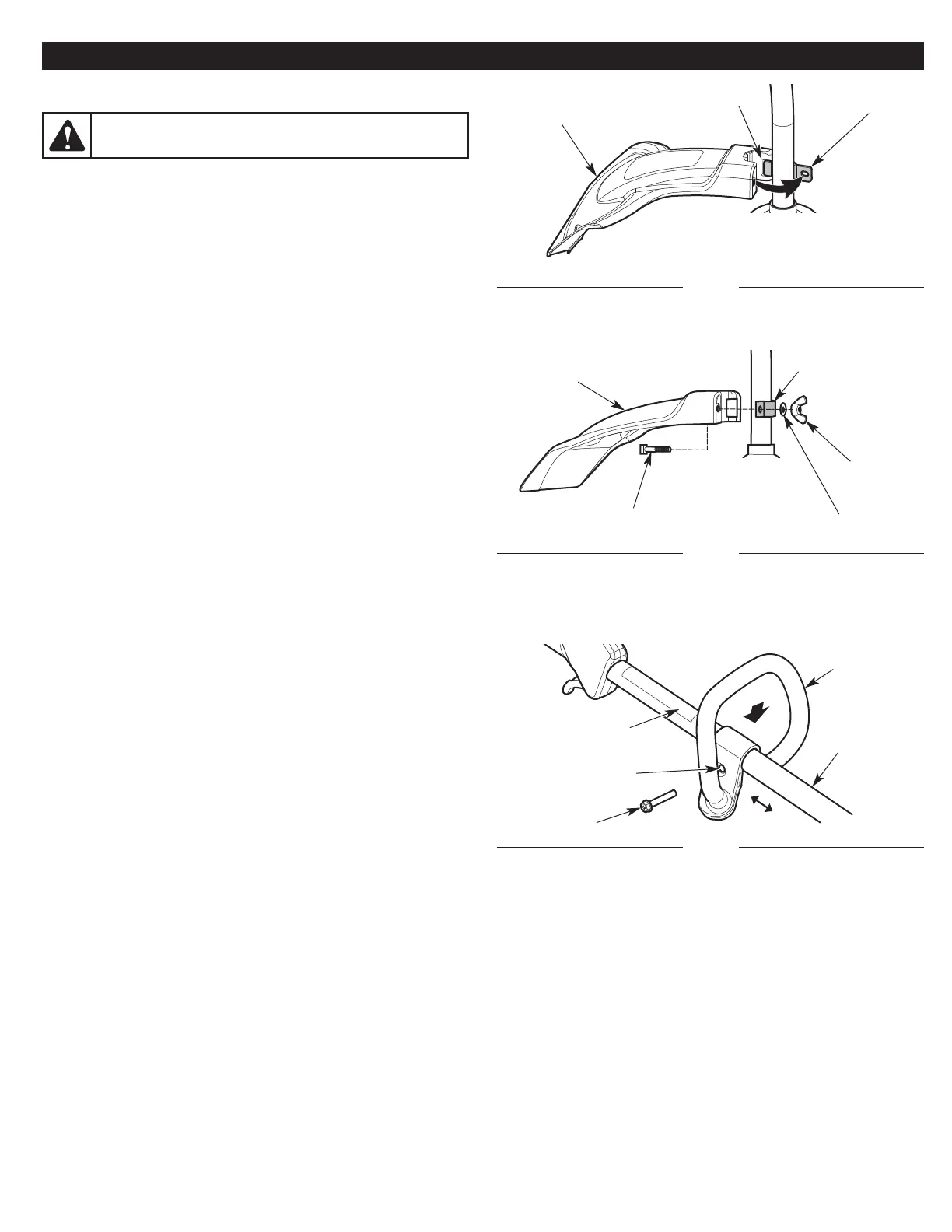
INSTALLING THE CUTTING HEAD SHIELD
1. Remove the wing nut and washer from the cutting head shield.
2. Insert the short tab (the one without a hole) on the mount
bracket into the slot on the cutting head shield (Fig. 1).
3. Rotate the cutting head shield counterclockwise to align the hole
on the cutting head shield with the hole on the mount bracket
(Fig. 1).
4. Insert the square bolt into the hole underneath the cutting head
shield (Fig. 2). Push the square bolt through the cutting head
shield and mount bracket.
5. Put the washer onto the square bolt (Fig. 2).
6. Screw the wing nut onto the square bolt until the cutting head
shield is firmly in place (Fig. 2).
Fig. 1
Mount Bracket
Cutting Head
Shield
WARNING:
To prevent serious personal injury, never
operate the unit without the cutting head shield in place.
Fig. 2
Washer
Square Bolt
Slot
Wing Nut
Cutting Head
Shield
Mount Bracket
INSTALLING AND ADJUSTING THE HANDLE
Installing the Handle
1. Push the handle down onto the shaft housing (Fig. 3). Make sure
the bolt hole faces to the right (Fig. 3).
2. Insert the bolt into the bolt hole and push it through (Fig. 3).
Tighten the bolt with a flat-head screwdriver, but do not tighten
the bolt completely .
3. Hold the unit in the operating position (Fig. 10) and move the
handle to a comfortable location (Fig. 3). Make sure the handle is
positioned beyond the end of the safety label (Fig. 3).
4. Tighten the bolt with a flat-head screwdriver until the handle is
secure.
Adjusting the Handle
If the handle requires adjustment:
1. Loosen the bolt with a flat-head screwdriver (Fig. 3).
2. Hold the unit in the operating position (Fig. 10) and move the
handle to a comfortable location (Fig. 3). Make sure the handle is
positioned beyond the end of the safety label (Fig. 3).
3. Tighten the bolt with a flat-head screwdriver until the handle is
secure.
Fig. 3
Bolt Hole
Handle
Shaft
Housing
Bolt
Safety Label