ENGLISH
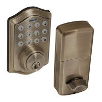
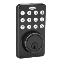
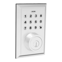
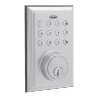
Models 1740032, 1740034, 1740036, 1740038
A
G H I J K
B C
D
E F
Installation OverviewTesting Operation
8
Before Opening Door
Let Motor Complete Cycle
Install Batteries and Cover7
B
This Electronic lock requires (4) High Quality AA Alkaline
batteries. When all 4 batteries are installed in the correct
position, you should hear 2 beeps and the keypad will
illuminate.
NOTE: Do not touch the Keypad until the light turns off.
Do not use rechargeable batteries or non-alkaline batteries.
Install Enclosed Latch and Strike Plate21 Determine Door “Handing”3
CB
Remove Screw to Remove Mounting Plate
Right Handed Door Turn Knob VerticalLeft Handed Door Turn Knob Horizontal
OR
View from outside of door
Set entry Switch to
Correct Direction
Install Exterior Assembly4
Install Interior Assembly
5
3/4” Screws1” Screws 5/16” Screws1 3/8” Screws
Exterior Faceplate Interior Faceplate
User Guide
Keys
Latch
Optional Set Screw
Mounting Plate
Preparing Door
Strike plate
1 - Exterior Faceplate
1 - Interior Faceplate
1 - User Guide
2 - Keys
1 - Strike Plate
1 - Mounting Plate
1 - Latch
1 - 1 3/8” Screws
2 - 5/16” Screws
2 - 1” Screws
5 - 3/4” Screws
1 - Electronic Remote
Package Includes:
Read this manual carefully before installing and operating!
Please carefully check the above list to confirm all items have been received. If any items are
missing, please contact Consumer Assistance. (See page for contact information)
J
Strike Plate
E
J
2-3/4” position
E
2-3/8” position
Do Not Over Tighten
Deadbolt Latch Must Be
Retracted During Installation
TO CONVERT FROM 2-3/8” (60mm) BACKSET TO 2-3/4” (70mm) BACKSET
1. Hold latch with numbers facing forward and thumb pressing on the bolt.
2. Rotate the cylinder cover clockwise.
3. Pull and twist the extension plate all the way out.
4. Rotate the cylinder counter clockwise so that the marking aligns with
the 2-3/4” position indicator.
NOTE: Do not extend Cylindrical Cover past 2-3/4” (70mm)
C
B
Carefully insert control wire
into the wire connector
Work with the door open
NOTE: Make sure the connector dots line up with the dots on the wire
Install Interior Assembly
6
Test the lock
Lock and unlock using the knob make sure the latch is opening and
closing easily. If not, go back to step 2 and ensure you followed the steps
NOTE: Make sure the Knob is in the correct position.
Be careful not to pinch the control wire when assembling
I
G
C
B
Refer to Template included for
Door Prep Instructions
F
NOTE: Skip this step if your door comes with pre-drilled holes.
Example
Remote
A
C
B
D
E
K
F
J
H
I
G
A
Check that the Rubber Gasket is secured on the Exterior
Assembly. Insert the Exterior Assembly onto the door with
the tailpiece going through the Deadbolt Latch Set in the
VERTICAL POSITION. Route the Control Wire through the
door under the Deadbolt Latch Set.
Secure mounting
plate to door
K (optional)
H
C
A
Test unlocking
Press 1-2-3-4-
Test the lock button with door open
M1740032 1740034 1740036 1740038 FH E V2