AIS CTRX GRAPHENE Class B AIS Transponder Manual
1.4E 20 CTRX GRAPHENE Manual
INSTALLATION
Once you have unpacked the box and checked that your delivery is complete,
proceed with the installation as follows:
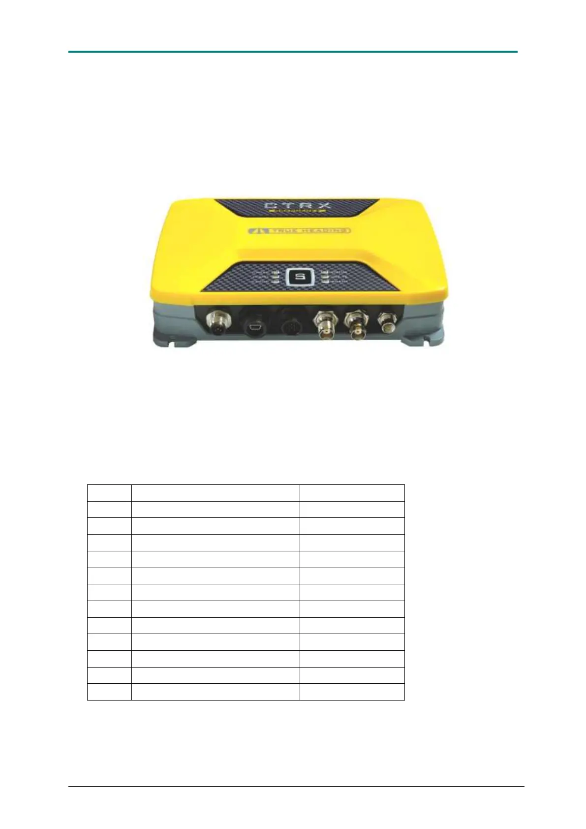
Figure 5 AIS CTRX GRAPHENE + with its antennas and data/DC connectors
The 12 pole multi-pin connector mounted on the transponder has the following
configuration of the pins:
Power supply Voltage GND (-)
NMEA 0183/RS-422 TX B (-)
NMEA 0183/RS-422 TX A (+)
NMEA 0183/RS-422 RX A (+)
Power supply Voltage GND (-)
NMEA 0183/RS-422 RX B (-)
Table 1. Data/DC connector configuration
 Loading...