14
Fig. 28
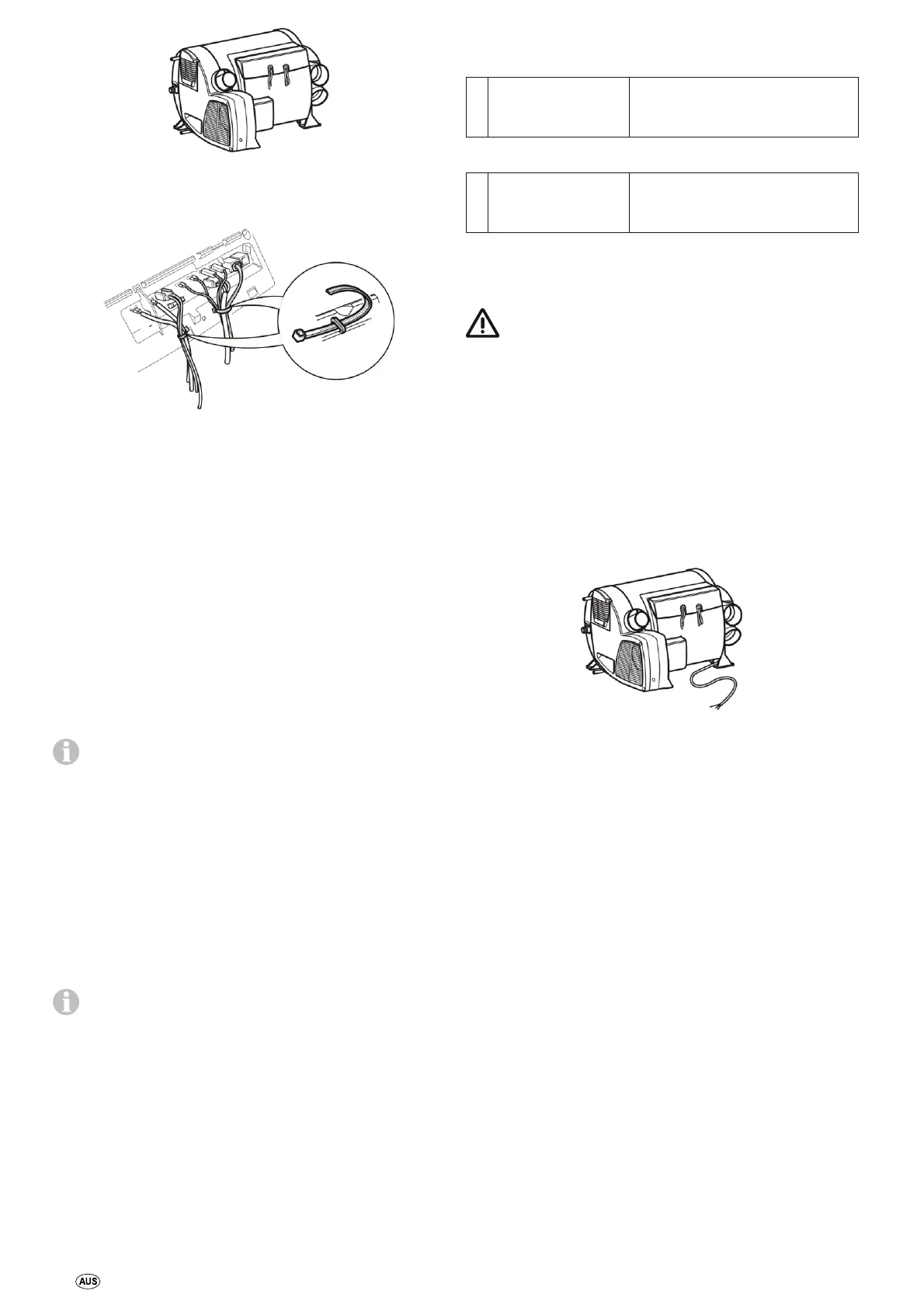
The connecting cables and plugs must not be subjected to force.
Bundle connecting cables (see figure 29) and secure each one to
housing using a cable binder in order to provide strain relief.
Fig. 29
All cables must be securely attached and must not become loose or
disconnected due to vibration – risk of fire!
12 V voltage supply
Electric cables, switching units and control units for heaters must be
arranged in the vehicle in such a way that their satisfactory
operation cannot be adversely affected under normal operating
conditions. All cables leading to the outside must be splash proof at
the leadthrough opening.
Prior to working on electric components the appliance must be
disconnected from the power supply. Switching off at the control
panel is not sufficient!
When carrying out electric welding work on the body the appliance
connection must be disconnected from the vehicle electrical system.
The unit is equipped with reverse polarity protection. If the
unit is connected with incorrect polarity, there will be
no display on the LED. The unit can be used after establishing proper
polarity.
To guarantee optimum power supply, the heating system must be
connected to the fused on-board network (central electronics unit
10 A) with a 2 x 2.5 mm² cable (for lengths over 6 m with 2 x 4 mm²
cable). If relevant, voltage drops in the supply cable must be taken
into account. Connect the negative lead to the central earth. If
connected directly to the battery, the positive and negative leads
must be fused. For the connections (40, 41), we recommend 6.3 mm
fully insulated flat connectors.
Do not connect any other consumers to the supply line!
When power packs or power supply units are being used,
note that the output voltage is between 11 V and 15 V and
the alternating current ripple is < 1.2 Vpp. We recommend the
automatic chargers from Truma for the different applications. Please
ask your dealer. Other chargers may be used only with a 12 V
battery as a buffer.
Room temperature sensor
Attach plug of connecting cable to connection (46 – no need to
observe polarity).
Control panel / air conditioning system
The following connecting combinations are possible.
Combi 2 E / 4 E CP plus (Australia)
(heater with electrical heating
elements)
Suitable systems – see
CP plus control panel operating
instructions
Insert the plug of the connecting cable into one of the connections
(47 or 48) and engage.
240 V voltage supply
The 240 V ~ electrical connection must always be made by
an expert (in accordance with e.g. IEC 603647-721). The
instructions shown here do not constitute a request to non-experts
to make the electrical connection but serve as additional
information for an expert who is employed to do the work!
It is imperative for the connection to be made with care using the
correct colours!
An insulating device for providing all-pole insulation from the
mains with contact clearance of at least 3.5 mm must be provided
by the customer for carrying out maintenance and repair work.
Make connection to power supply by attaching 150 cm long silicon
cable to a line that is protected with as least 10 A (16 A would be
better).
Fig. 30
All cables must be secured with cable clips.
Function test
After installation, the gas feed line must be tested for tightness by
the pressure-drop method.
Then test all functions of the unit as described in the operating
instructions, particularly the drainage of the water contents. There
shall be no claims under guarantee for d amage caused by frost!
The operating instructions must be handed over to the vehicle
owner.
Warnings
The installer or vehicle owner must apply the yell ow sticker with
the war ning information, which is enclosed with the appliance, to a
place in the vehicle where it is clearly visible to all users (e.g. on the
wardrobe door)! Ask Dometic to send you stickers, if necess ary.