9
Regulations
Guarantee claims, warranty claims and acceptance of liability will be
ruled out in the event of the following:
– modifications to the unit (including accessories),
– modifications to the exhaust duct and the cowl,
– failure to use original Truma parts as replacement parts and
accessories,
– failure to follow the installation and operating instructions.
It also becomes illegal to use the appliance, and in some countries
this even makes it illegal to use the vehicle.
In-vehicle installations must comply with the technical and
administrative regulations of the respective country of use (e.g.
AS/NZS 5601.2 for vehicles). The national regulations and rules must
be complied with.
More information on the regulations in the relevant destination
countries can be requested from our foreign representatives (see
Truma Service Booklet or www.truma.com).
Selecting a location
The unit and its exhaust duct must always be installed so that they
are easy to access at all times for service work (e.g. gas and water
connection via a service flap, furniture doors etc.) and are easy to
remove and install.
The distance between the unit and surrounding furniture items or
vehicle components must be at least 10 mm at all sides.
The flue and warm air ducts can be installed without clearance.
Make sure that there is at least 10 mm clearance to combustible
materials around the warm air discharge vent and 500 mm in front
of the vent. Locate the vent so that curtains, bedding, etc. cannot be
blown directly in front of or in contact with the warm air vent.
For warm air ducting only Truma ductings have to be
installed.
The scope of delivery includes a second type plate (duplicate) with
removable bar code.
If the type plate on the heater is not visible after the heater has
been installed, the second type plate (duplicate) must be affixed to
the unit in a clearly visible location.
The duplicate must only be used in conjunction with the original.
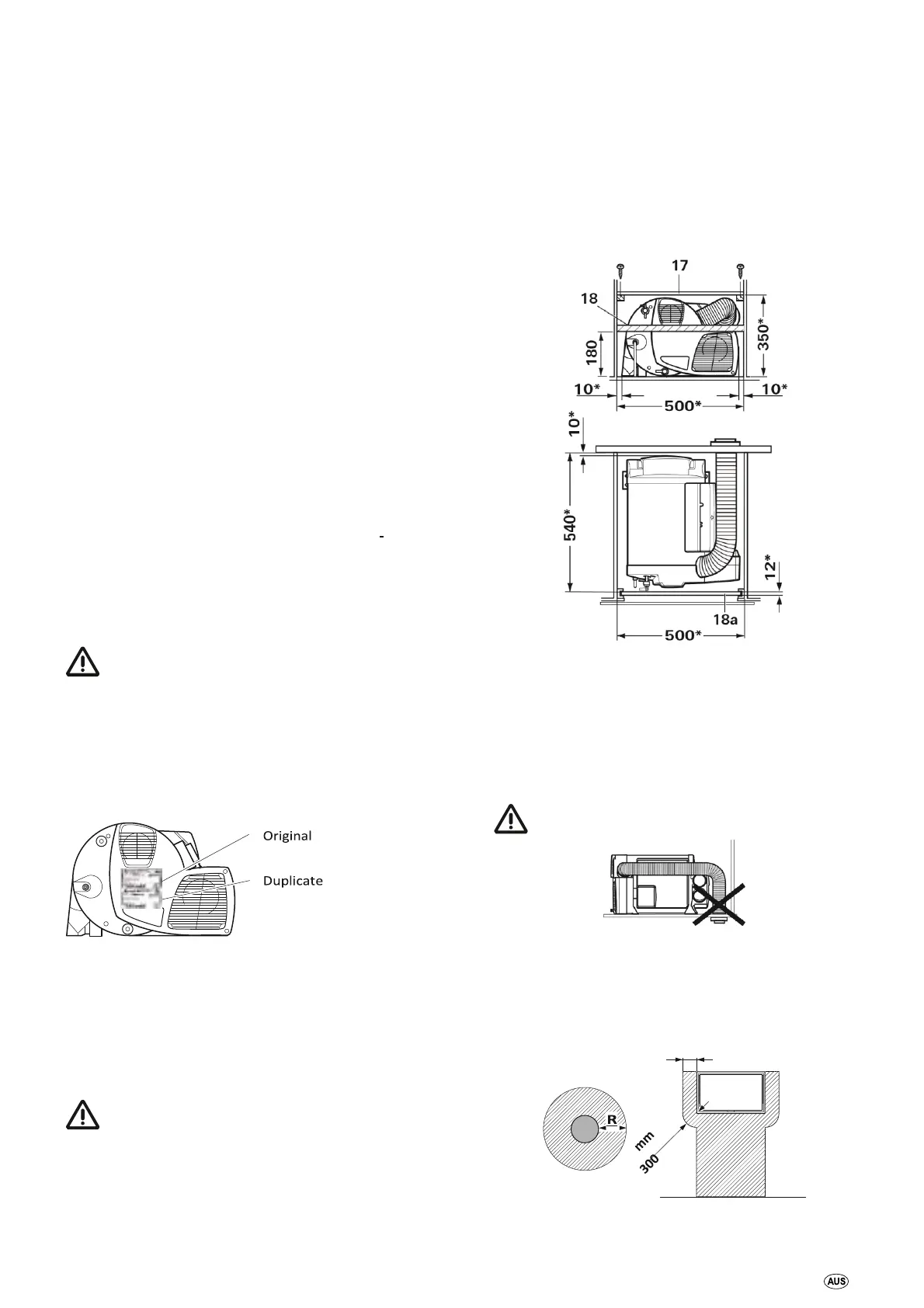
Fig. 9
In order to heat the vehicle evenly throughout, the heater must be
installed in a location in the vehicle that is as central as possible in
a wardrobe, stowage compartment or the like with an adequate
height, so that the air distribution ducts can be routed with equal
lengths. Appropriate openings must be present in the installation
compartment so that air can be drawn in – see relevant sections
concerning circulated air intake and warm air distribution.
In order to reduce the potential danger caused by a heater
becoming loose in the event of an accident, the
upper covering plate (17) of the installation cabinet can be screwed
to other pieces of furniture in a position that makes it flush with the
heater. Depending on the installation situation, it may be necessary
(especially with rear-mounted fixtures) to install a stable furniture
console (18) in front of (next to) the heater, perpendicular to the
direction of travel. For this purpose, a solid spacer (minimum cross s
ection 30 x 50 mm) can be attached at a height of approx. 180 mm
above the floor, or a board (18a) for sliding in on a stable furniture
console.
There must not be any heat-sensitive materials beneath the unit
(e.g. floor coverings such as PVC, cables etc.), since high
temperatures can occur at the base of the unit.
In order to prevent damage to components inside the equipment,
no cables or water lines of any kind may be attached to the
equipment’s insulation.
The operation of important vehicle components must not be
adversely affected.
Fig. 10
* Minimum dimensions – additional space must be p rovided for the
gas connection, water connections and the FrostControl
depending on the installation situation. All dimensions in mm.
The cowl must be placed in such a way that exhaust gas cannot find
its way into the vehicle interior.
The cowl must be in the form of a wall or roof cow
Fig. 11
The wall or roof cowl must be attached such that there is no fuel
tank filler neck or fuel tank breather opening within 500 mm (R).
There must also be no living area ventilation openings or window
openings within 300 mm.
300 mm
Fig. 12