40
34020-01190 - 01 - 03/2022
Installation Combi D
EN
The connector cables and plugs must not be subjected
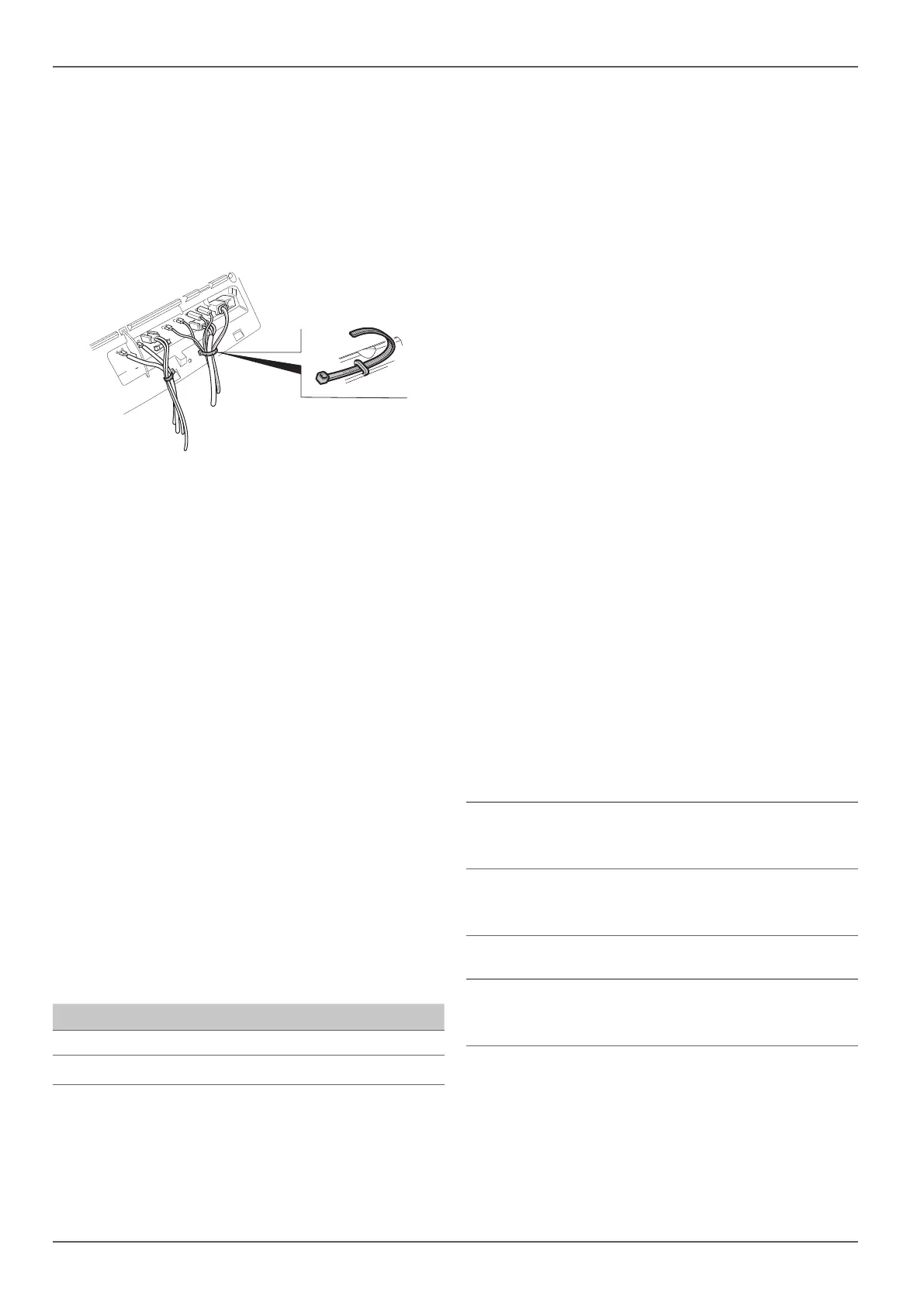
to force. For strain relief, bundle the connector cables
(see Fig. 42) and fasten each bundle to the housing
with a cable tie.
DANGER
Risk of fire
Cables can become loose through vibration.
Fasten all cables securely.
Fig. 42
2.11.1 12 V voltage supply
Electric cables and switching and control equipment
for heaters must be in locations that will not cause the
operation thereof to be adversely affected under normal
operating conditions. The openings for all cables lead-
ing to the outside must be protected from spray water.
Disconnect the appliance from the power supply before
starting to work on electrical components. Switching
off at the control panel is insufficient.
The appliance must be disconnected from the on-board
power supply when electric welding work is being car-
ried out on the body.
The appliance has reverse polarity protection. The
LED indicator will not work if the appliance is con-
nected with incorrect polarity. The appliance can be
re-used when the correct polarity is restored and
both appliance fuses have been replaced. To replace
the fuses, refer to “Maintenance and servicing” in
the operating instructions.
To ensure an optimum power supply, the heater must
be connected to the fused on-board supply (fuse in the
central electronics 20 A). Voltage drops in the supply
line must be taken into consideration if applicable.
Cable length Cross-section
0.0 m – 5.0 m 2 x 4.0 mm²
5.0 m – 7.5 m 2 x 6.0 mm²
Connect the negative wire to the vehicle's earth
cable. If the equipment is connected directly to the
battery, the positive and negative lines must be pro-
tected. We recommend fully insulated 6.3 mm flat
connectors for the connections. Ensure that the flat
connectors are firmly connected.
No other consumers must be connected to the supply
line!
NOTICE
Damage to the heater electronics caused
by irregular power supply from solar panels
When a solar system is used, EN1648 stipu-
lates that a battery (with charge regulator) or a
voltage regulator (output voltage 11 V-15 V;
alternating voltage ripple< 1.2 Vss) must be
connected between the solar system and the
heater at all times.
When disconnecting the battery, always
disconnect the charge regulator from the
battery first.
When connecting the battery, always con-
nect the charge regulator to the battery last.
No warranty claims will be accepted for heater electron-
ics that are damaged as a result of an irregular power
supply from the solar panels.
If you are using grid or power supply devices, make
sure that they deliver a controlled output voltage be-
tween 11 V and 15 V and that the AC ripple voltage
is < 1.2 Vss. For the different applications, we rec-
ommend the Truma BC 10 charger. Only use charg-
ers with a 12 V battery as a buffer.
2.11.2 Room temperature sensor
Attach the plug of the connector cable to the con-
nection (Fig. 40-5) (polarity is not important).
2.11.3 Control panels
The following connection combinations are possible.
Digital control panels
Truma iNet X (Pro) Panel
Combi D (all models) (heater
with / without electric heat-
ing rods)
Truma CP plus
Combi D (all models) (heater
with / without electric heat-
ing rods)
Analog control panels
Truma CP classic
Combi D 4 / D 6 (all mod-
els) (heater without electric
heating rods)
Insert the plug of the respective connector cable into
one of the connections (Fig. 40-6 or Fig. 40-7) and
engage it.


 To Next Page
 Loading...