Do you have a question about the Truma Mover SE and is the answer not in the manual?
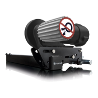
Key safety precautions for operating the Mover.
General information about the Mover's capabilities and usage.
Recommendations and guidelines for suitable batteries for the Mover.
Explanation of the Mover's operational functions and components.
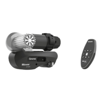
Details on the remote handset's buttons, indicators, and operation for SE/TE models.
Interpreting LED flash codes and acoustic signals from the remote.
Instructions for replacing batteries in the remote handset.
Step-by-step guide to maneuvering the caravan using the Mover.
Guidance on using the Mover to position the caravan for hitching.
Routine maintenance procedures and regular checks for the Mover system.
Manual procedure to swivel drive rollers out in emergencies.
Common issues and solutions for Mover operation.
Details on warranty coverage, exclusions, and claims procedures.
Conditions and exclusions covered under the manufacturer's warranty.
Details on the duration and coverage of the warranty.
Procedure for making a warranty claim.
Specifies the Mover's intended application and official approvals.
Lists the necessary tools and equipment for installation.
Outlines the spatial requirements for fitting the Mover.
How to measure chassis height and determine the correct installation type.
Details on different chassis types and required mounting kits.
Information on installing special accessories like spacer plates.
Specifics on low chassis kits and AL-KO Vario III/AV installation kits.
Details on the mounting set for Eriba Touring chassis.
Restrictions on chassis modifications and compatibility.
Guidance on selecting the optimal installation location for the Mover.
Step-by-step instructions for installing the drive units.
How to correctly position drive rollers and use spacer plates or flat frame kits.
Steps for installing motor cables and the control unit.
Visual guide for connecting the Mover's electrical components.
Instructions for connecting the drive motors to the control unit.
Instructions for connecting the swivel-in motors.
How to install the isolating switch and connect the battery.
Connecting the safety socket for conventional brake lights.
Connecting the 13-pin safety socket to the controller.
Wiring diagram for LED brake lights and safety socket.
Connecting the 7-pin safety socket to the controller.
Final steps to check and commission the Mover system.
| Type | Caravan Mover |
|---|---|
| Operating voltage | 12 V DC |
| Control | Remote control |
| Drive Type | Friction roller |
| Model | Mover SE |