34020-01190 - 01 - 03/2022
Combi D Installation
39EN
2.9 Installing the room temperature
sensor
When choosing a location, please note that the room
temperature sensor must not be subjected to direct
heat radiation. In order to obtain optimum room tem-
perature control, install the room temperature sensor
above the entrance door.
Ensure that the sensor is always installed on a vertical
wall. There must be a free flow of interior air around the
sensor.
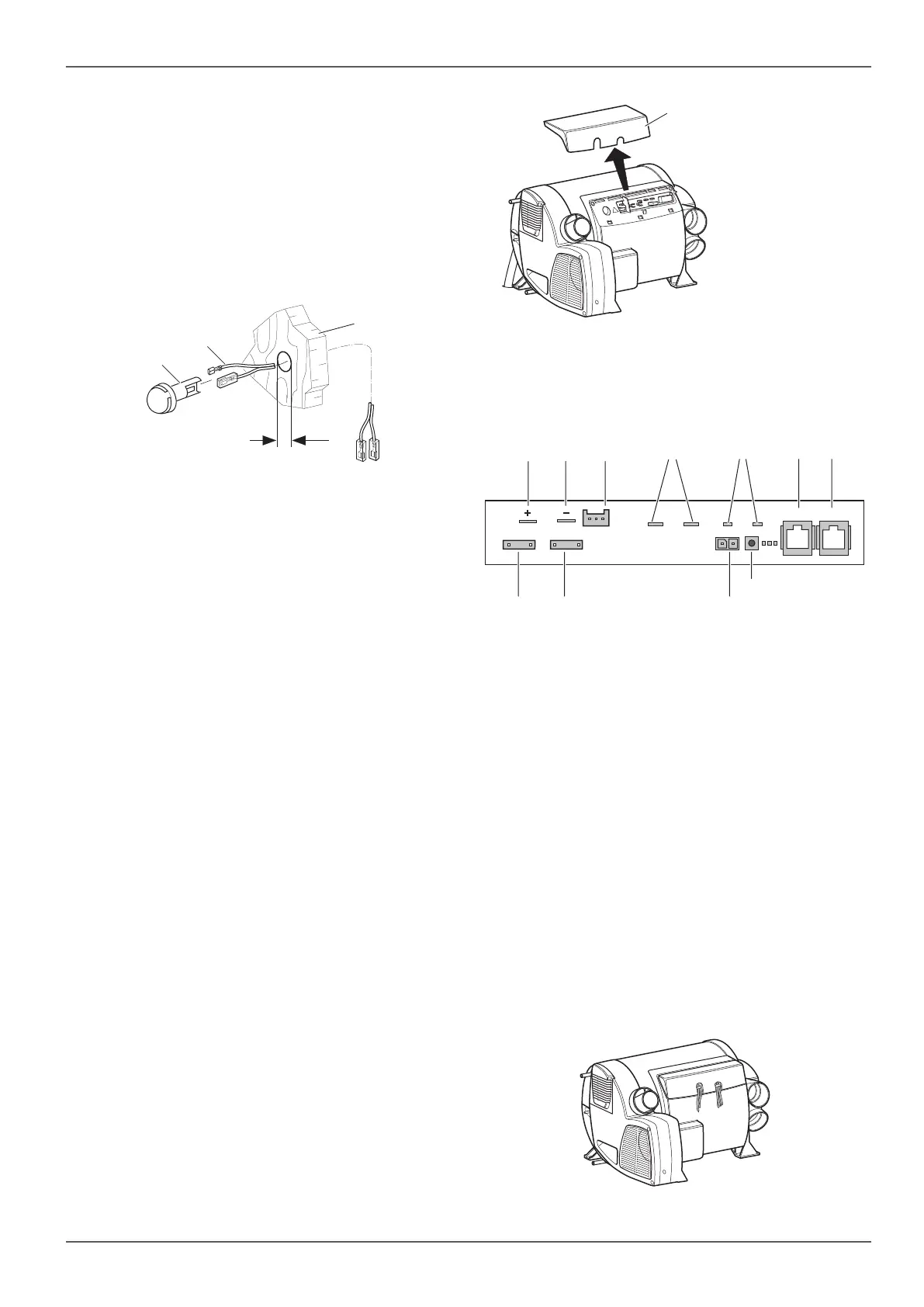
3
2
1
a
Fig. 38
Drill a hole with a diameter of 10 mm. Feed the con-
nector cable (Fig. 38-2) through the hole from be-
hind and connect the end of the cable to the sensor
with an insulated connection plug (Fig. 38-1) (polari-
ty is not important).
Slide in the room temperature sensor and connect
the end of the cable to the heater electronics with
the two insulated connectors (extend cable to a
maximum total length of 10 m with 2x0.5 mm²
cable if required).
With a Truma iNet X (Pro) Panel, refer to the instal-
lation instructions for wiring the room temperature
sensor. With all other control panels, the room tem-
perature sensor must always be connected, other-
wise the heater will show a malfunction.
2.10 Fitting the control panels
Installation of the control panels is described in the in-
stallation instructions provided with the control panel.
2.11 Electrical connections
Lay connector cables so that they cannot chafe. On
sharp edges, such as holes through metal walls, use
additional lead-through bushings or edge protection.
Do not fasten connector cables to metal surfaces of
appliances, to the exhaust duct or to warm air ducts.
Connector cables must not touch these.
The electrical connections are beneath the connector
cover (Fig. 39-1) of the heater. It can be removed by
pressing and simultaneously pulling in the direction of
the arrow.
1
Fig. 39
When removing or replacing the connector cover, pay
attention to connector cables so that you do not pull
them out or squash them.
RTS
Window
Reset
TIN TIN
FC
12V
F101 10A
F100 10A
DP
1010
3 42 51 76
9 108
11
Fig. 40
1 Input voltage +12 V (spade connector 6.3 mm)
2 Input voltage, earth (spade connector 6.3 mm)
3 FrostControl heating element (accessory)
4 Wire bridge (or window switch – accessory)
5 Room temperature sensor
6 Control panel / diagnose tool / other approved
Truma device1
7 Control panel / diagnose tool / other approved
Truma device1
8 Flat fuse 10A
9 Flat fuse 10A
10 Metering pump
11 Reset button
Alternative connections
All connections to the appliance should be made with sag-
ging connector cables. This will stop condensation running
down the connector cables and into the appliance.
Fig. 41


 To Next Page