38
34020-01190 - 01 - 03/2022
Installation Combi D
EN
20 mm
45º
1
3
4
2
5
Fig. 35
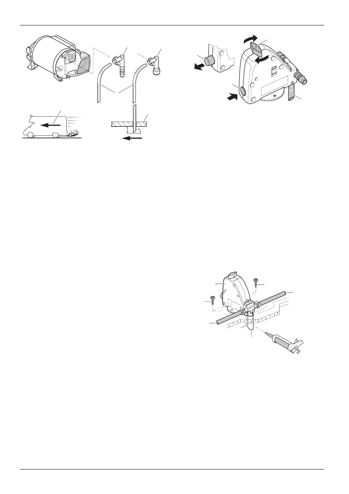
Slide the venting hose with an outer diameter
of11 mm (Fig. 35-3) onto the hose nozzle of the
aeration valve and route outdoors without any kinks.
The radius of arc must not be less than 40 mm.
Feed the venting hose through a drilled hole in the
floor of the vehicle and cut it at a 45° angle to the
driving direction approximately 20 mm below the
floor (Fig. 35).
2.8.3 Incorporating the FrostControl (safety /
drain valve) in the water system
TB (for hose rubber connection) and JG (for fixed duct
routing) are available.
The FrostControl must be installed in the cold water
supply system. It protects the heater against frost at
low temperatures and also protects the water system
against critical high pressure.
DANGER
Scalding from hot water
A critical high pressure can occur due to high
temperatures. This can cause hose rubber con-
nections to become loose and scald people with
hot water.
Connect the hoses carefully and check the
connections.
The FrostControl must be installed close to the appli-
ance inside the vehicle at a place that is easily acces-
sible for the user. Make sure that the rotary switch
(Fig. 36-3) and pushbutton (Fig. 36-1) and (Fig. 36-2)
can be operated.
4
1
2
3
Fig. 36
NOTICE
Frost damage
When selecting a location, please ensure that
the FrostControl (Fig. 37-1) is not installed
near external heat sources (e.g. power sup-
plies) or directly beside warm air ducts.
Water removal can take place directly to the outside
in a splash-protected location.
Drill a hole (18 mm diameter) in the floor of the
vehicle.
Slide the hose (Fig. 37-6) onto the drainage sockets
(Fig. 37-5), push both through the floor to the out-
side of the vehicle.
Align the drainage socket centrally to the hole.
Secure the FrostControl with two B 5.5 x 25 screws
(included with delivery) without tension. Screw in
the screws vertically.
Seal the gap between the hose and the hole with
plastic body sealant from below (Fig. 35).
1
2
3
2
4
6
7
5
Fig. 37



 To Next Page