34020-01190 - 01 - 03/2022
Combi D Installation
37EN
1
2
6
5
4
3
78
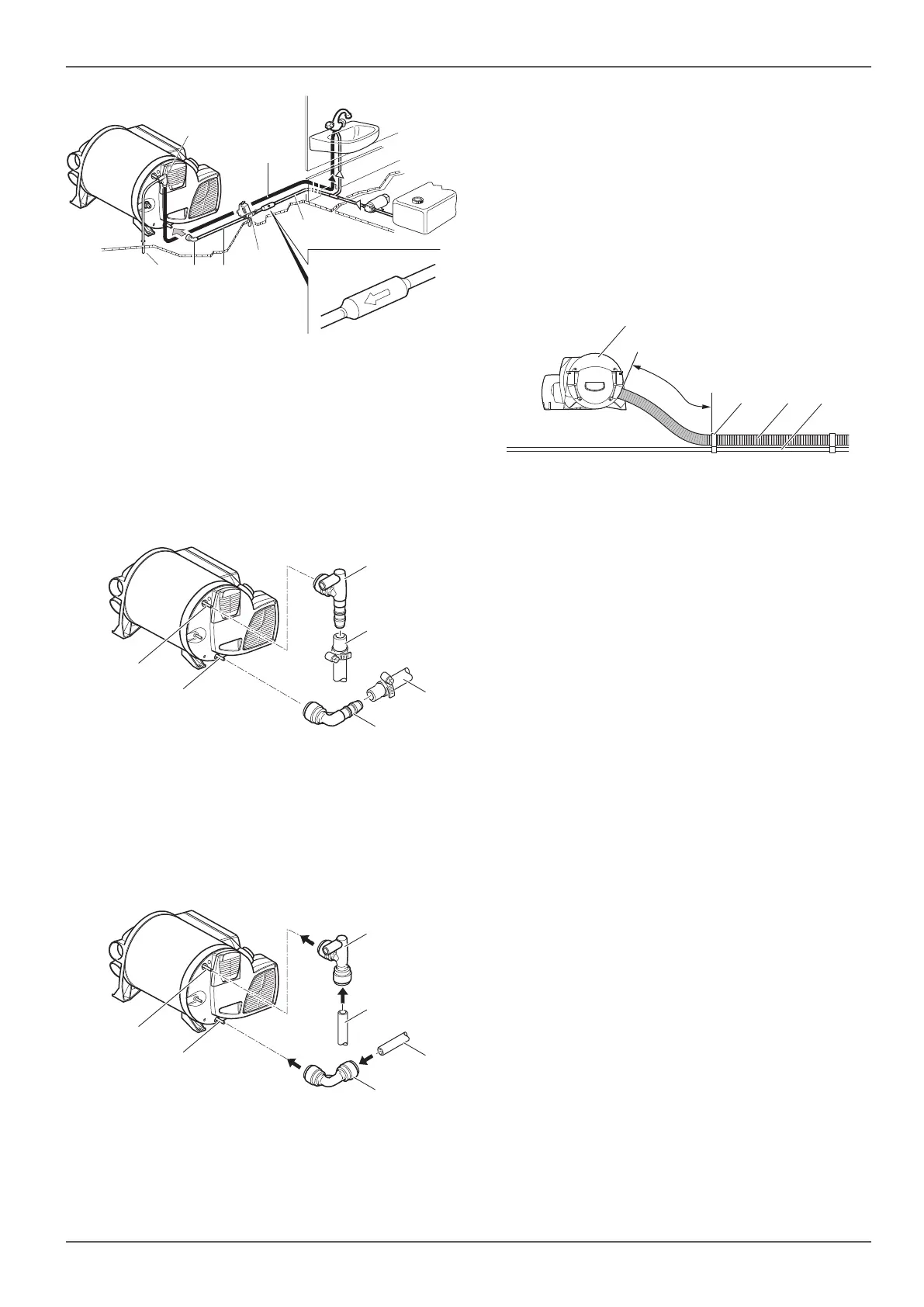
Fig. 31
2.8.2 Connecting the Combi D to the water
system
Installation with flexible hoses (Ø 10 mm)
The TB elbow fittings (Fig. 32-3) and (Fig. 32-6) and the
safety / drain valve (Fig. 30-5) have a Ø 10mm connec-
tion. All hose connections must be secured with hose
clamps (including the cold water connection).
4
2
1
3
5
Fig. 32
Installation with fixed duct routing (Ø 12 mm)
The JG elbow fittings (Fig. 33-3) and (Fig. 33-6) and the
safety / drain valve (Fig. 30-5) have a Ø 12 mm interior
connection. We recommend the use of John Guest
ducts, insertion sleeves and retaining rings. Appropriate
adapters are available for connecting ducts with differ-
ent diameters (not included in scope of delivery).
4
2
1
3
5
Fig. 33
In order to ensure that the connected components will
work, the water pipes must be kept as short as possible
and be free of kinks and strain.
Install all water pipes sloping downward towards the
safety / drain valve. No claims may be made under
the warranty for damage caused by frost.
•
If a water supply is being installed in the vehicle, it
must be ensured that sufficient room is left between
the water lines and the heat source (e.g. heater,
warm air duct).
a
32
1
4
Fig. 34
A water pipe (Fig. 34-4) may only be installed on the
warm air duct (Fig. 34-3) at a distance of 2 m from the
heater. The hose clip SC (part no.: 40712-01) (Fig. 34-2)
can be used from this distance. With parallel routing
(e.g. through a wall) a spacer (e.g. insulation) must be
fitted in order to avoid contact.
Due to the risk of frost, make sure that the cold wa-
ter supply does not come into contact with thermal
bridges (e.g. the external wall).
Connect the cold water supply (Fig. 37-4) to the
safety / drain valve (Fig. 37-1).
To ensure that all the water is drained and that the
water hoses on the appliance do not leak, always
use the supplied elbow fittings (Fig. 32-3) and
(Fig. 32-6) or (Fig. 33-3) and (Fig. 33-6).
Install the water pipe (Fig. 37-3) for the cold water
supply between the safety / drain valve and the inlet
on the water container.
Install the water pipe (Fig. 32-4) or (Fig. 33-4)
for hot water from the elbow connection valve
(Fig. 35-1 or 2) to the consumption points.
Attach the elbow connection valve to the top con-
nection of the heater (hot water discharge) and the
elbow fitting (Fig. 32-6) or (Fig. 33-6) to the bottom
connection (cold water supply) of the heater as far
as it goes. Pull in the opposite direction to ensure
that the elbow fittings are securely attached.



 To Next Page