36
34020-01190 - 01 - 03/2022
Installation Combi D
EN
Connecting the heater and metering pump to the
fuel line
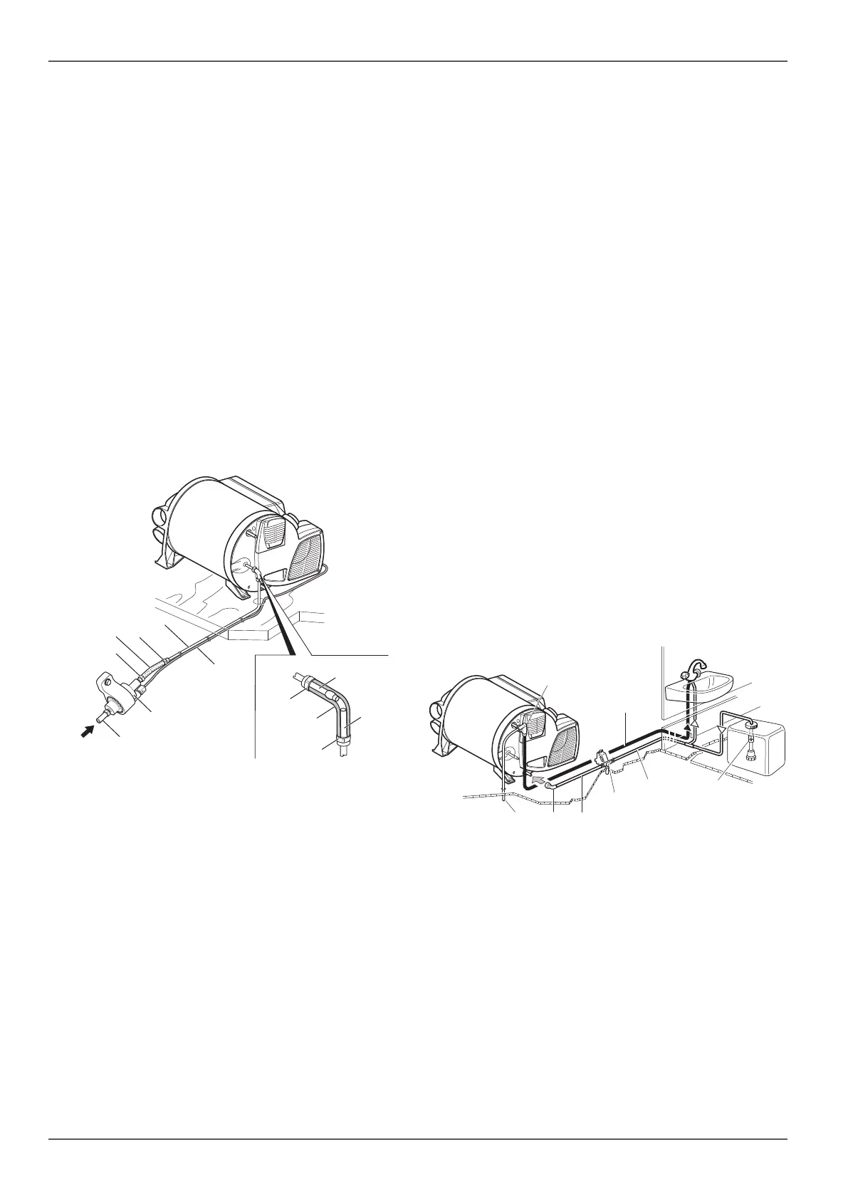
Mark the hole for the fuel line (Fig. 29-5) and the me-
tering pump connector cable (Fig. 29-5) in a suitable
location on the floor of vehicle.
Before drilling, always check for underlying / con-
cealed cables, fuel lines, frame sections and the like.
Lay the fuel line and connector cable of the meter-
ing pump (Fig. 29-6) so that they cannot chafe. Use
lead-through bushings or edge protection on sharp
edges, such as holes in metal walls.
Connect the fuel line to the heater and metering
pump.
Fasten the fuel line (Fig. 29-5) together with the
connector cable (Fig. 29-6) to the vehicle with the
supplied hose holders or loosely with cable ties
(approx. every 50 cm).
If the fuel lines touch parts of the vehicle or if the ca-
ble ties are too tight, this will cause transmission of
metering pump sounds (clicking).
3
4
2
1
7
5
3
5
6
4
3
3
Fig. 29
1 Fuel line (from vehicle tank)
2 Metering pump
3 One-ear clamps (11.1 – 13.1mm)
4 Adapter Di 5mm / L 50mm NBR
5 Fuel line (pressure line)
6 Connector cable
7 Fuel line connection Combi D
2.8 Water connection
2.8.1 Pumps in the water system
General
Any pressure or immersion pump up to 2.8 bar can be
used to operate the water container, as can any mixing
battery with or without an electric switch.
If the system is connected to a central water supply
(town water), or if a more powerful pump is used, install
a pressure reducer to prevent pressures higher than
2.8 bar in the water container.
Before the pressure relief valve triggers, warming
of the water and its resulting expansion may cause
pressure of up to 4.5 bar to occur (also possible with
immersion pumps). The water pipes for connecting
to the water container and the safety / drain valve
must be drinking water safe, pressure resistant
(upto 5 bar) and hot water resistant up to +80 °C.
If the water container is connected to a central
water supply (town water), a non-return valve
(part no. 70000-03300 or 70020-03300) must be in-
stalled to ensure that non-drinking water cannot flow
back or be sucked back into the central water supply
from the vehicle.
Immersion pumps
If immersion pumps are used, a non-return valve (not
included in scope of delivery) (Fig. 30-3) must be in-
stalled between the pump and the first branch. Observe
the direction of flow when installing the non-return
valve.
8
1
3
4
2
5
67
Fig. 30
Pressure pumps
If pressure pumps with large switching hysteresis are
used, hot water can flow back through the cold water
tap. We recommend installing a non-return valve (not
included in scope of delivery) between the outlet to the
cold water valve and the safety / drain valve to prevent
back-flow (Fig. 31-4). Observe the direction of flow
when installing the non-return valve (Fig. 31-4).


 To Next Page