34020-01190 - 01 - 03/2022
Combi D Installation
35EN
2.7.2 Installing the metering pump
•
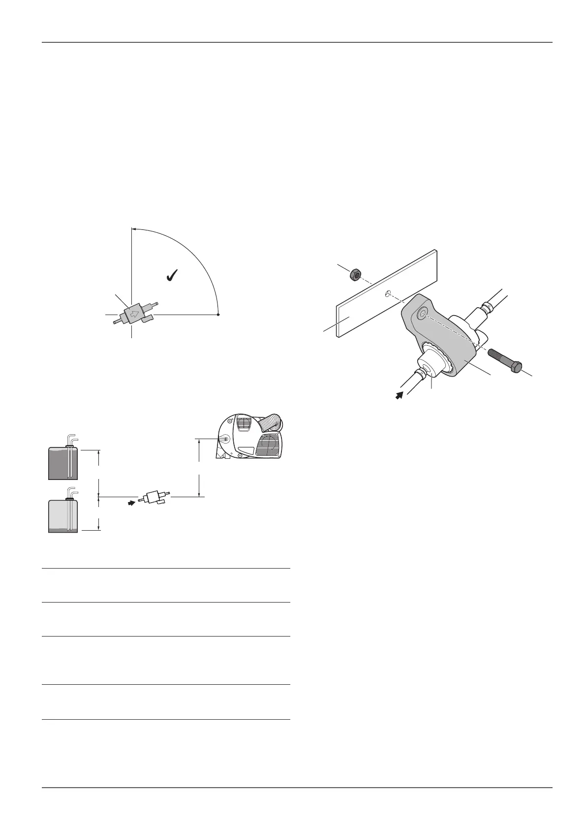
Always install the metering pump (Fig. 26-1) with the
pressure side (delivery direction) sloping upwards.
•
Do not drill into the vehicle's chassis.
•
Do not mount the metering pump on the vehicle's
chassis.
Protect the metering pump (Fig. 26-1) from heating
up (max. operating temperature 40°C); therefore do
not install it in the vicinity of sound mufflers or ex-
haust ducts.
Metering pump installation position
0˚
90˚
1
Fig. 26
Permissible metering pump intake and pressure
levels
b
c
a
Fig. 27
Pressure level from fuel tank to
metering pump
a = max. 1500 mm
Intake level with depressurised
fuel tank:
b = max. 1000 mm
Intake level with fuel tank in
which negative pressure oc-
curs during removal (valve with
0.03 bar in tank cap): b = max. 400 mm
Pressure level from metering
pump to heater:
c = max. 2000mm
Fastening the metering pump
Find a suitable position on the vehicle.
Do not drill any holes contrary to the specifications
of the vehicle manufacturer.
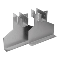
Slide the metering pump (Fig. 28-2) into the bracket
(Fig. 28-3) and centre it.
Screw the bracket and metering pump onto a suita-
ble position on the vehicle (Fig. 28-1).
Clamp the suction and pressure line with one-ear
clamps.
Align the metering pump so that it slopes slightly
upward.
Tighten the screw (Fig. 28-4).
2
1
4
5
3
Fig. 28


 To Next Page