34
34020-01190 - 01 - 03/2022
Installation Combi D
EN
2.7.1 Installing the fuel lines
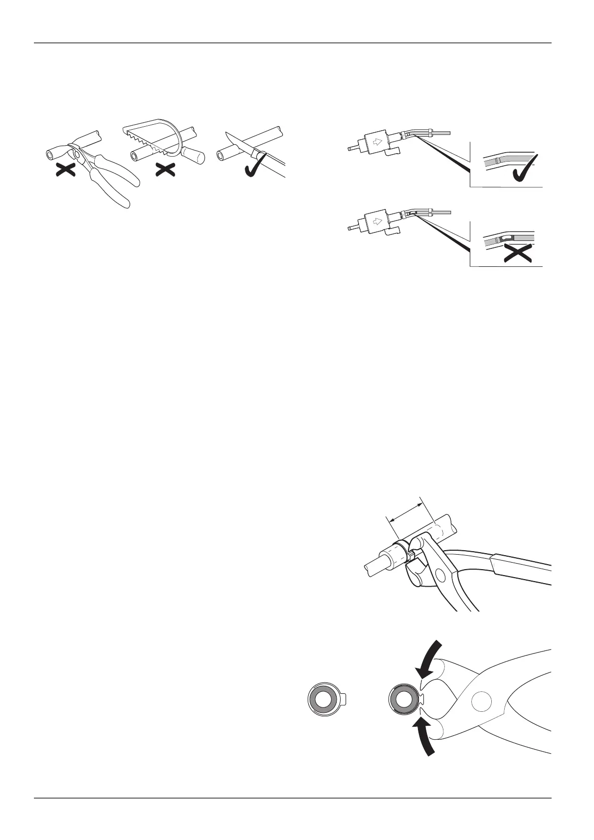
Shorten fuel lines only with a sharp knife (Fig. 22). The
cut areas must not be compressed and must be free of
burrs.
Fig. 22
Fuel lines must be securely attached in order to prevent
damage and/or noise generation caused by vibration
(recommended spacing between attachment points
approx. 50 cm).
Fuel lines must be protected from mechanical damage.
Route fuel lines so that vehicle twisting, engine move-
ments and the like do not adversely affect the stability
thereof.
WARNING
Risk of fire
Never route or secure fuel lines immediately
adjacent to the exhaust ducts of the heater
or of the vehicle engine.
If the lines cross, maintain an adequate dis-
tance away from hot components – provide
heat radiation protection panels if necessary.
Connecting fuel lines and the metering pump
with an adapter
If fuel lines are connected with an adapter, the fuel lines
must connected end to end. This prevents problematic
bubbles forming.
1
2
Fig. 23
1 Correct line routing
2 Incorrect line installation (bubbles forming)
Slide single ear clamps onto both ends of the
adapter.
Slide the adapter onto the connection of the meter-
ing pump as far as it goes.
Slide the fuel line into the adapter.
Position the single ear clamps, making sure that the
fuel line extends at least 15 mm beyond the single
ear clamps (Fig. 24).
Crimp the single ear clamps with the assembly pliers
(Fig. 25).
Fig. 24
Fig. 25


 To Next Page