34020-01190 - 01 - 03/2022
Combi D Installation
33EN
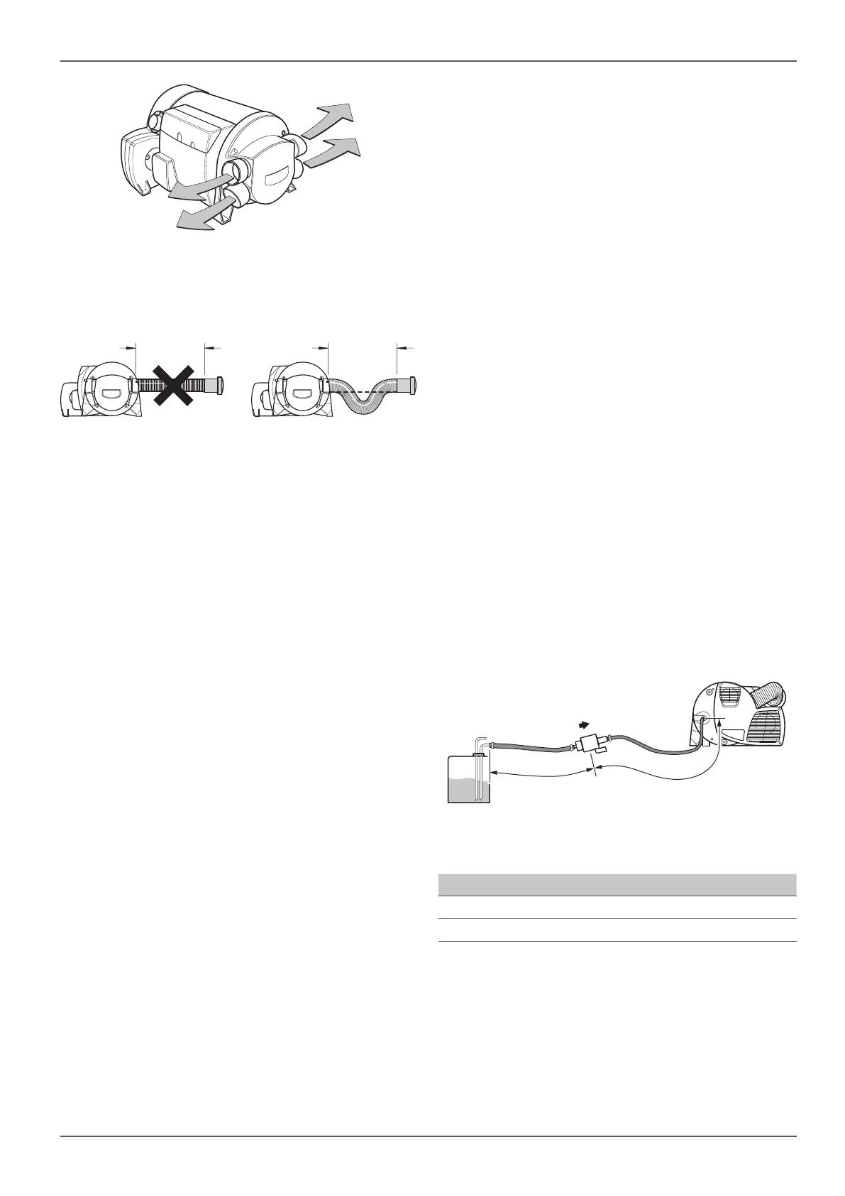
Fig. 19
With a duct length of less than 2 m, the outlet must not
be installed higher than the warm air duct connection.
If the duct is shorter than 50cm, the duct between the
connection and the outlet must form a trap.
Fig. 20
In hot water mode, these measures prevent undesired
heating of the vehicle through convection.
The ducts for warm air distribution must be firmly
inserted into the connections. A clip is attached to
each connection to provide a more secure grip.
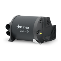
For optimum warm air distribution, Truma always rec-
ommends using the 4 warm air outlets of the heater. If
just 3 warm air outlets are required, one of the lower
warm air outlets must be closed with a blank cover CB,
black (part no. 34310-01).
Press the blank cover firmly into the moulded part of
the heater until you hear it engage and it sits firmly
Check for firm seating.
CAUTION
Potential heat accumulation
Connect warm air ducts to all warm air con-
nections that are used.
Do not reduce the cross section of the warm
air ducts by squeezing them together or
similar.
If a closable end outlet is installed (e.g. in the
bathroom) in a warm air line, install a second
warm air outlet in this warm air line that can-
not be closed.
The warm air system is designed individually for each
vehicle type using the modular design principle. A wide
range of accessories is available for this purpose.
2.7 Fuel connection
•
DIN EN 590-compliant diesel fuel is needed to oper-
ate the heater.
•
Fuel may be removed only from a vented, unpressur-
ised fuel tank.
•
The metering pump must never be connected to the
vehicle's fuel lines due to the static and dynamic
pressure relationships there.
•
Connect the metering pump to the vehicle's fuel
tank with a vehicle-specific tank connection kit in
accordance with the installation instructions.
•
The connection can be made with the parts includ-
ed with the delivery if the vehicle manufacturer has
prepared the chassis for direct connection of an
additional heater with the help of a fuel line (5mm
outer diameter). In this case, follow the instructions
in the annex.
Other Truma tank connection kits are available from
the Truma product range.
WARNING
Risk of fire due to wrong installation
Pressures around the pump input of more than
300 mbar to the environment feed fuel into the
appliance even when the heater is turned o.
This will cause a malfunction and produce large
amounts of smoke that could ultimately result in
a fire hazard.
Do not connect the fuel line to pressurised
pipes or fuel tanks.
Observe the maximum lengths of the fuel line – 2 m
for the suction side and 6 mfor the discharge side.
ba
Fig. 21
Measurement Value
a max. 2m
b max. 6m


 To Next Page