2
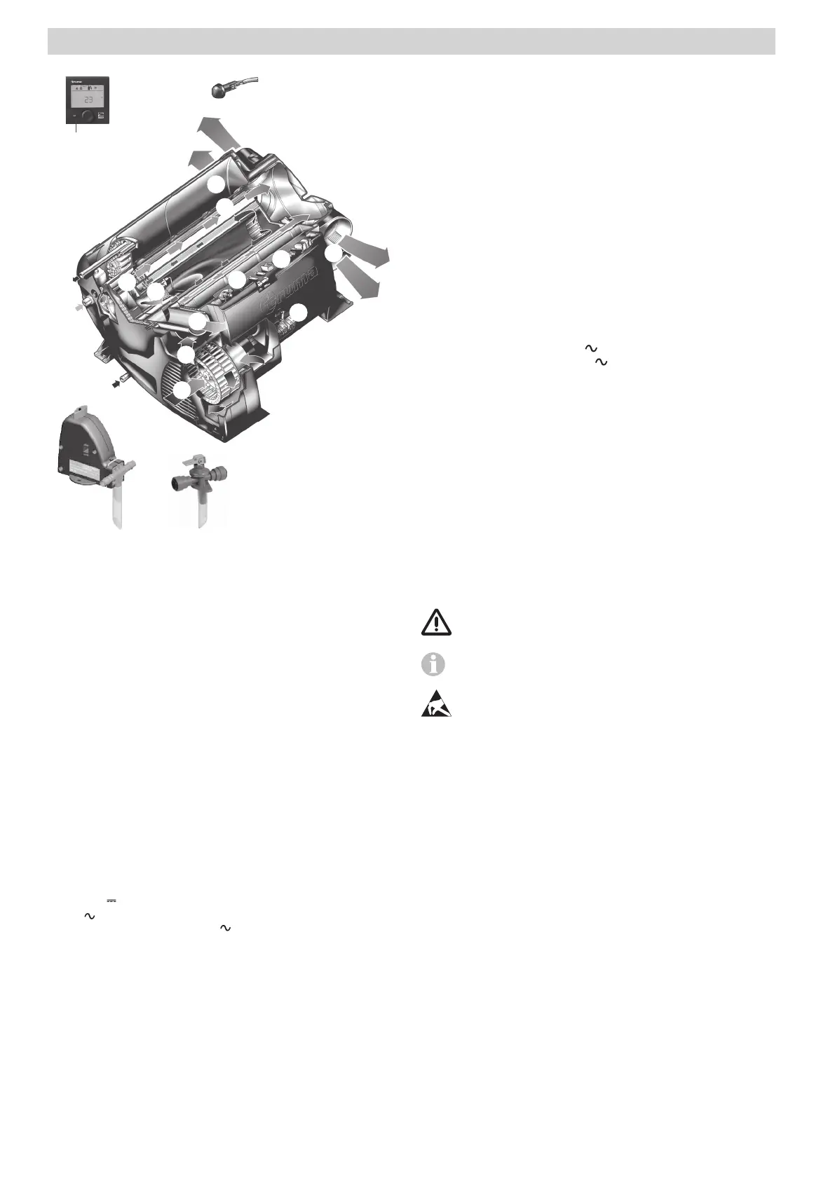
1 Digital or analogue control panel (no picture)
2 Room temperature sensor
3 Cold water connection
4 Hot water connection
5 Gas connection
6 Warm air outlets
7 Circulated air intake
8 Exhaust gas discharge
9 Combustion air infeed
10 Electronic control unit
11 Water container (10 litres)
12 Burner
13 Heat exchanger
14 Power electronics
15 Heating elements 230 V
16 Overheating switch 230 V
17 FrostControl (safety/drain valve – UK version optional)
18 Safety/drain valve (UK version)
Combi (E)
Geändert Ludsteck 2017
17 18
2
3
5
7
8
9
11
10
14
15
16
4
12
13
6
6
1
Figure 1
Symbols used
Symbol indicates possible hazards.
Note containing information and tips.
Observe the ESD regulations!
Table of contents
Symbols used ........................................................................ 2
Intended use ....................................................................... 3
Safety instructions ............................................................ 3
Function description (Combi) ............................................ 6
Function description (Combi E) ......................................... 6
Operating instructions
Control panels .................................................................... 7
Room temperature sensor ................................................ 7
Safety/drain valve .............................................................. 7
A. FrostControl ..................................................................... 7
B. safety/drain valve ............................................................. 8
Filling the boiler ................................................................. 8
Draining the boiler ............................................................. 8
Start-up ................................................................................ 9
Switching off ...................................................................... 9
Maintenance ....................................................................... 9
Solar systems ..................................................................... 9
Fuses .................................................................................... 9
Fuse 12 V ........................................................................... 9
230 V fuse (Combi E) ........................................................ 9
Overheating protection 230 V (Combi E) ........................ 10
Technical data ................................................................... 10
Dimensions ......................................................................... 10
Disposal ............................................................................. 10
Faults .................................................................................. 11
Troubleshooting guide (water supply) ................................. 11
Accessories ....................................................................... 11
Manufacturer’s Warranty
(European Union) .............................................................. 12