EasyManua.ls Logo

Truma CP plus VarioHeat - User Manual

Truma CP plus VarioHeat
20 pages
Print Icon
To Next Page IconTo Next Page
Loading...
Operating instructions Page 2
Installation instructions Page 16
To be kept in the vehicle.
This document is part of the product.
FIRE OR EXPLOSION HAZARD
Failure to follow safety warnings exactly
could result in serious injury, death or prop-
erty damage.
Do not store or use gasoline or other flam-
mable vapors and liquids in the vicinity of
this or any other appliance.
WHAT TO DO IF YOU SMELL GAS
Evacuate all persons from the vehicle.
Shut off the gas supply at the gas contain-
er or source.
Do not touch any electrical switch or use
any phone or radio in the vehicle.
Do not start the vehicle’s engine or electric
generator.
Contact the nearest gas supplier or certi-
fied service technician for repairs.
If you cannot reach a gas supplier or certi-
fied service technician, contact the nearest
fire department.
Do not turn on the gas supply until gas
leaks have been repaired.
Installation and service must be performed
by a certified service technician, service
agency, or the gas supplier.
Digital control panel
4010007
Truma CP plus VarioHeat

Questions and Answers

  • M
    Madison BrewerAug 2, 2025
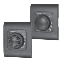
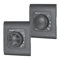
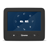
    What to do if Truma CP plus VarioHeat Control Panel displays error E 2 H E 16 H?
    • P
      Peter MartinezAug 2, 2025
      If the Truma Control Panel displays error code E 2 H E 16 H, it means the flame was not detected. This could be due to an empty gas cylinder. Replace the gas cylinder. It may also be that the gas cylinder or quick-acting valve in the gas supply line is closed. Check the gas infeed and open the valves. High butane concentration in the gas cylinder may be the cause. Use propane instead, as butane is unsuitable for heating, especially below 10 °C. Finally, the combustion air infeed or exhaust gas outlet might be blocked. Check the openings for any dirt (slush, ice, or leaves) and clear them.
  • D
    Daniel CurryAug 7, 2025
    Why does my Truma Control Panel show error code W 255 H?
    • D
      Daniel AtkinsonAug 7, 2025
      The W 255 H error code on your Truma Control Panel indicates that the heater isn't receiving 12 VDC power or there's no connection between the heater and the control panel. First, ensure that the 12 VDC power supply is active. Next, verify and establish the connection between the heater and the control panel.
  • D
    Daniel FernandezAug 12, 2025
    What to do if Truma Control Panel displays error W 27 H?
    • L
      Luis RodriguezAug 12, 2025
      If your Truma Control Panel shows error code W 27 H, it indicates a blockage. Check the warm air outlets, the circulated air intake, and the EN end outlet for any obstructions. Remove any blockage from the warm air outlets and the circulated air intake. Ensure the EN end outlet is open.
  • T
    Toni GreenAug 17, 2025
    Why does my Truma CP plus VarioHeat show error code W 26 H?
    • T
      traci90Aug 17, 2025
      The Truma Control Panel displaying error code W 26 H indicates undervoltage, meaning the battery voltage is too low (below 10 VDC). To resolve this, charge the battery or replace it if it's old.
  • J
    John MezaAug 22, 2025
    How to fix Truma Control Panel error W 25 H?
    • K
      kimberlystuartAug 22, 2025
      If your Truma Control Panel is showing error code W 25 H, it means there's excess voltage (above 16.4 VDC). Check the battery voltage and power sources, including the battery charger.
  • L
    Lisa SmithAug 27, 2025
    What does error W 29 H mean on Truma CP plus VarioHeat?
    • C
      Chelsea CopelandAug 27, 2025
      The error code W 29 H on your Truma Control Panel indicates an imminent undervoltage situation, meaning the battery voltage is too low (below 10.4 VDC). Charge the battery to resolve this.

Summary

Safety Warnings

Fire or Explosion Hazard

Critical safety warning regarding fire and explosion hazards.

Consumer Safety Information

Safety Definitions

Defines safety alert symbols and terms like WARNING and NOTICE for hazard communication.

Safety Behavior and Practices

Provides essential safety guidelines for operating the control panel and appliance.

Operating Instructions

Display and Operating Elements

Details the physical components of the control panel and their functions.

Control Panel Operation

Explains the use of rotary push button and back button for navigation.

Initial Start-up

Step-by-step guide for the initial setup and initialization of the control panel.

Basic Operations

Covers selecting setting level, switching on/off, and changing room temperature.

Selecting Fan Speed

Guide to selecting and adjusting the fan speed for the heating system.

Hot Water Mode and Temperature

Instructions for changing hot water mode and setting desired temperature.

Setting the Time Switch

Procedure for configuring the time switch for automated heating operation.

Time Switch Settings

Configuring start/end times and enabling/disabling the time switch.

Room Temperature and Fan Speed

Setting room temperature and adjusting fan speed for heating.

Clock and Service Menu

Setting the clock and accessing service functions like sensor calibration.

Display and Language Settings

Adjusting temperature units, backlighting, time mode, language, and version display.

Factory Reset and Special Displays

Procedure for factory reset and information on special display indicators.

Warning and Error Handling

Managing warning/error indications, codes, and malfunctions.

Maintenance

Technical Data

Troubleshooting VarioHeat (H)

Troubleshooting AquaGo (W)

Installation Instructions

Safety Information

Crucial safety guidelines and precautions for installing the control panel.

Description

Overview of the control panel's connectivity and components.

Dimensions

Physical dimensions of the control panel unit.

Installation Location

Recommendations for choosing a suitable and accessible location for installation.

Wiring Diagram

Illustrates the electrical connections between the control panel and other components.

Connection

Details the procedures for connecting the control panel to the power supply and appliances.

Installation Procedure

Step-by-step guide for physically mounting and assembling the control panel.

Contact and Service Information

Truma CP plus VarioHeat Specifications

General IconGeneral
BrandTruma
ModelCP plus VarioHeat
CategoryControl Panel
LanguageEnglish

Related product manuals