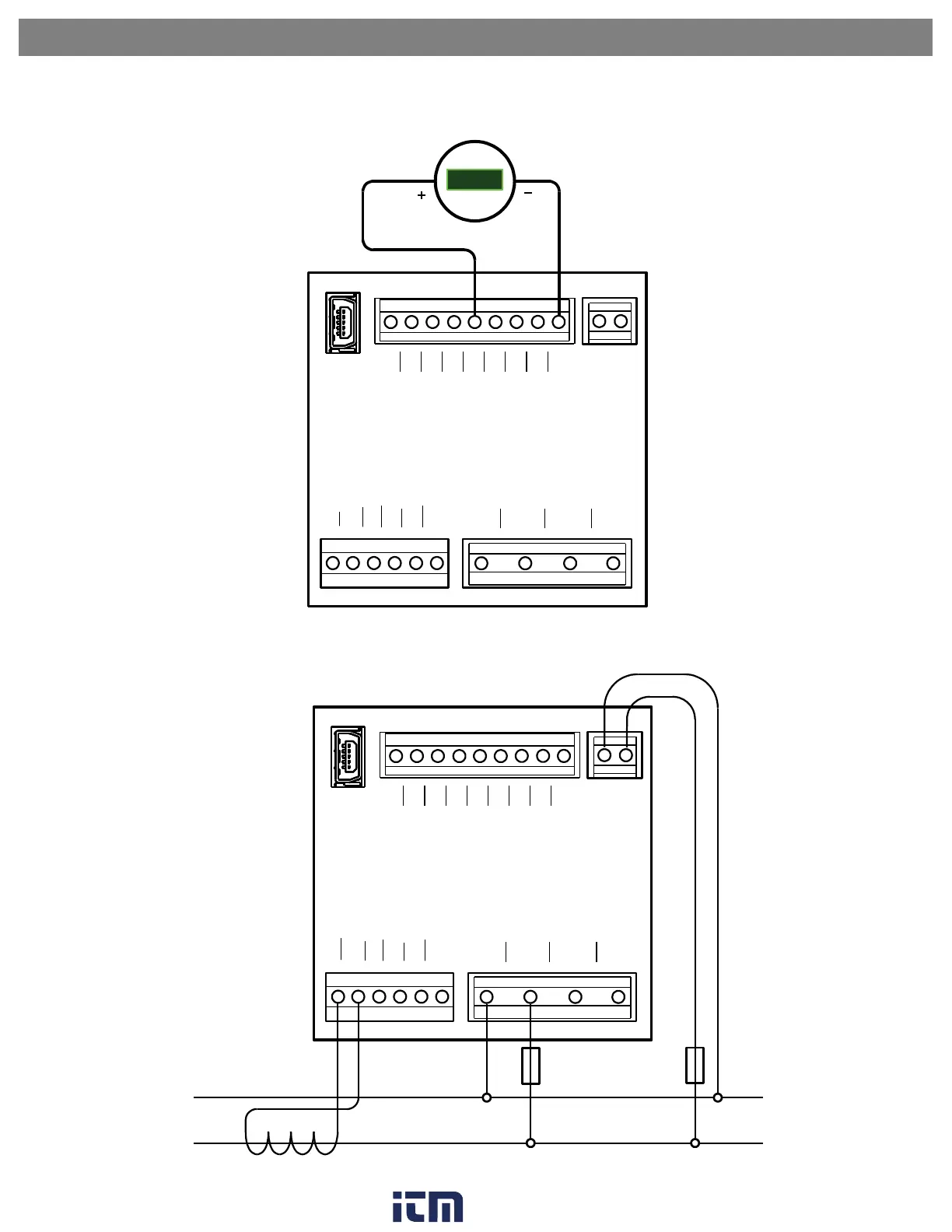
EasyManuals Logo

Trumeter APM User Manual

Trumeter APM
9 pages
To Next Page IconTo Next Page
To Previous Page IconTo Previous Page
Page #3 background imageLoading...
Page #3 background image
Wiring Diagrams
OP1-
OP1+
OP2-
OP2+
AOUT
NC
B
A
0V
N
L
PSU
USB
A1+
A1-
A2+
A2-
A3+
A3-
N
V1
V2
V3
CURRENT MEASUREMENT VOLTAGE MEASUREMENT
MODBUS AND OUTPUTS
ANALOG OUTPUT CONNECTIONS
4-20mA
+88.8
mA
SINGLE PHASE POWER METER CONNECTIONS - LINE POWER
OP1-
OP1+
OP2-
OP2+
AOUT
NC
B
A
0V
N
L
PSU
USB
A1+
A1-
A2+
A2-
A3+
A3-
N
V1
V2
V3
CURRENT MEASUREMENT VOLTAGE MEASUREMENT
MODBUS AND OUTPUTS
FUSE
LOAD
N
L
NOTE: DO NOT CONNECT CT SECONDARYS TO EARTH. CTS
EARTHED THROUGH N TERMINAL
L
SUPPLY
N
FUSE
w ww. . com
information@itm.com1.800.561.8187

Other manuals for Trumeter APM

Questions and Answers:

Question and Answer IconNeed help?

Do you have a question about the Trumeter APM and is the answer not in the manual?

Trumeter APM Specifications

General IconGeneral
Display TypeLCD
Supply Voltage12-24 VDC
Operating Temperature-10 °C
Dimensions96 mm
ProtectionIP65
DisplayLCD