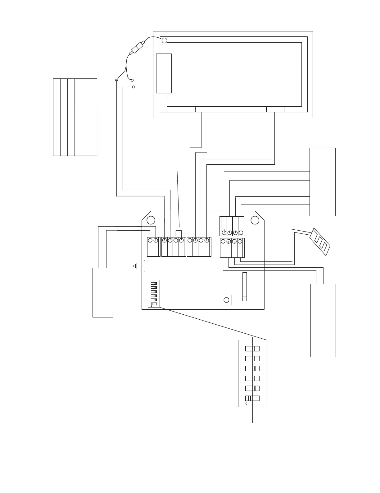
Grey
Green
Grey
Grey
Grey
Green
Green
Green
White
White
White
Grey
Grey
Red
Black
Blue
Blue
Blue
12
10
7
5
4
Motor
Lock 1
Lock 2
Red
Black
Red
Black
Screen
Interlock
Red
Black
Black
Black
Jumper
supplied
in kit
See Step 5
+
-
Blind motor
Security System
Close Command Status
+
-
+
-
S2
S1
1
2
34
5
6
on
off
Smoke Vent Control
J1
Open Command
Rain Sensor
White
White
S2
1
2
34
5
6
on
off
1 - Must stay set to "on"
2 - Motor Application:
Window application = "off"
Skylight application = "on"
3 - Drive motor direction to Open:
CW ="off" Or CCW = "on"
4 - Motorized Blind:
No Blind present = "off"
Blind connected = "on"
5&6 - Motorized lock s:
No locks = 5 & 6 both "off"
One lock = 6 "on" & 5 "off"
Two locks = 6 "off" & 5 "on"
Function Settings for Dip Switches:
Wire Size
(Class 2)
Total distance
from Control to
farthest motor
18 AWG
14 AWG
12 AWG
50 ft (15m) Max.
100 ft (30m) Max.
150 ft (60m) Max.
Solid Core Wire Recommended.
Refer to Class 2 codes
Earth Ground for accessories
Main Wiring Diagram