9
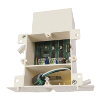
10. Connect Wires Per Wire Diagram
Connect low voltage wires to the control panel as outlined in wire diagram.
See Connection Blocks 1 thru 5.
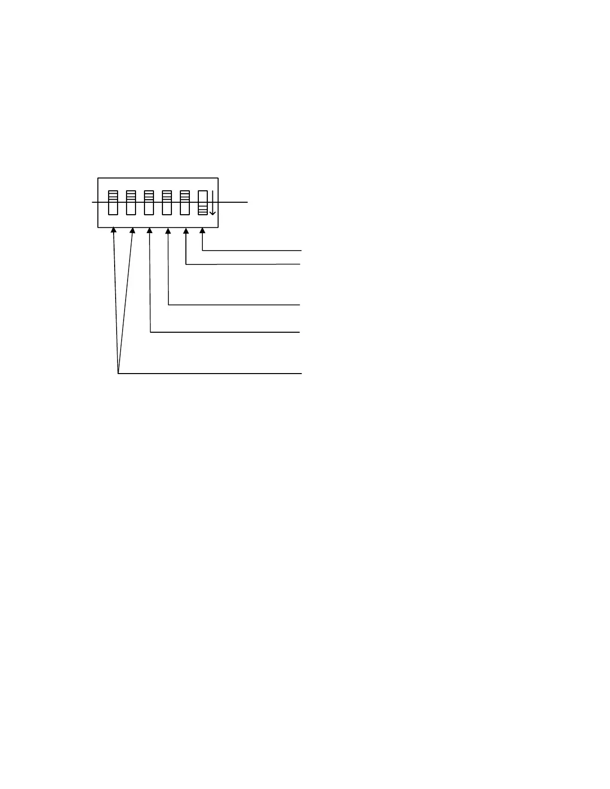
11. Set Function Dip Switches
The Function Settings on Dip Switch (See S2 on wire diagram) need to be configured for each
motor application.
1
2
34
5
6
on
off
1 – Must stay set to “on”
2 – Motor Application:
Window = “off”
Skylight = “on”
3 – Drive motor direction to open from Step 1a
CW = “off” OR CCW = “on”
4 – Motorized Blinds:
No Blind present = “off”
Blind connected = “on”
5 & 6 – Motorized Locks
No Locks = 5 & 6 both “off”
One Lock = 6 “on” & 5 “off”
Two Locks = 6 “off” & 5 “on”
Note: Dip switch settings should be made with Power disconnected.