Contents xi
Figures
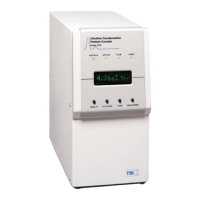
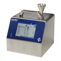
1-1 Model 3786 Ultrafine Water-based Condensation
Particle Counter (UWCPC) ...............................................1-2
1-2 UWCPC Flow Diagram ........................................................1-4
2-1 Location of UWCPC Wick on Sample Inlet Assembly ...........2-3
2-2 Installation of UWCPC Wick on Sample Inlet Assembly.......2-3
2-3 Fill Bottle Connection .........................................................2-4
2-4 Drain Bottle Connection .....................................................2-6
2-5 Tipping the UWCPC During Drain Cycle for More
Complete Drain of the Reservoir ......................................2-8
2-6 Location and Removal of Reservoir Cover............................2-9
4-1 UWCPC Data Communications Diagram.............................4-2
5-1 Location of Purge Flow Line ................................................5-2
Tables
2-1 Components of the Ultrafine Water-based Condensation
Particle Counter ..............................................................2-1
2-2 Replacement Parts for the Ultrafine Water-based
Condensation Particle Counter ........................................2-1
3-1 Front Panel Indicator Conditions ........................................3-5
4-1 Serial Connector Signal Connection....................................4-1