31
43
43
20
44
43
27
20
43
44
75
Reinforcement
Tubes
66
27
64
65
67
Note:
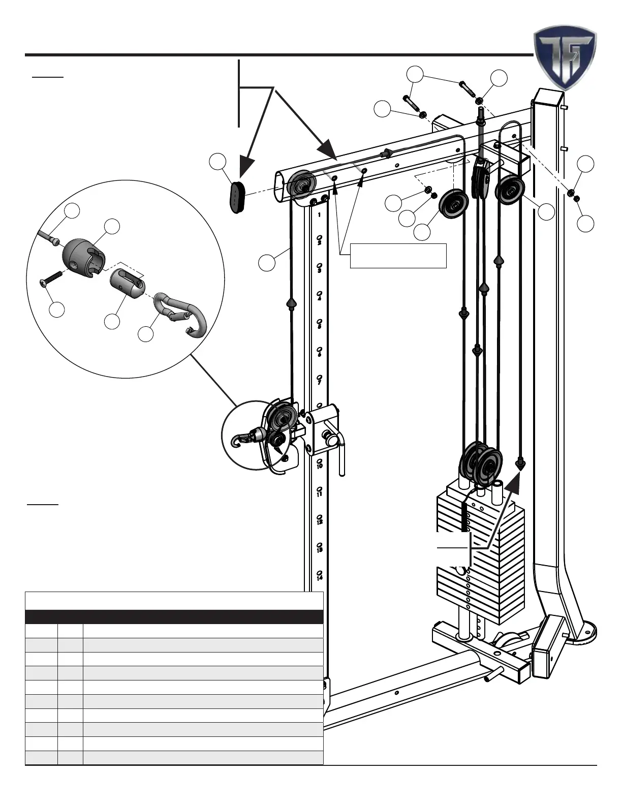
• Make sure the cable runs in the grooves of
the pulleys.
• It is strongly recommended that two people
participate in this assembly step.
• Some parts have been removed for Clarity.
Step 10 Top LEFT SIDE Cable Assembly
Step 10 Assembly List
Item Qty. Description
20 2 BLACK NYLON PULLEY WIDE GROOVE 3/8 X 1 X 3 1/2
27 1 CABLE CDP-300
31 2 HEX HEAD CAP SCREW GR-5 Z/P 3/8-16 X 2 9/16
43 4 FLAT WASHER SAE Z/P 3/8"
44 2 NYLON INSERT THIN PATTERN LOCK NUT Z/P 3/8-16
64 1 CABLE STOPPER SHELL 1 1/2 X 1 3/4
65 1 7/8 RD X 1 5/8 LINK 1/8 CABLE
66 1 OVAL HEAD SCREW Z/P #10-32 X 1 1/8
67 1 SNAP LINK Z/P 8MM X 80MM
75 1 PLASTIC INSERT CAP ELLIPTICAL 2 X 4
Note:
Continue on Next Page.
Note:
Install Plastic Insert Cap #75 after
Making sure the Cable is running
over the two Reinforcement Tubes.
23CDP-300 Dual Adjustable Pulley System W/150 lbs Weight Stacks
www.tuffstuffi tness.com