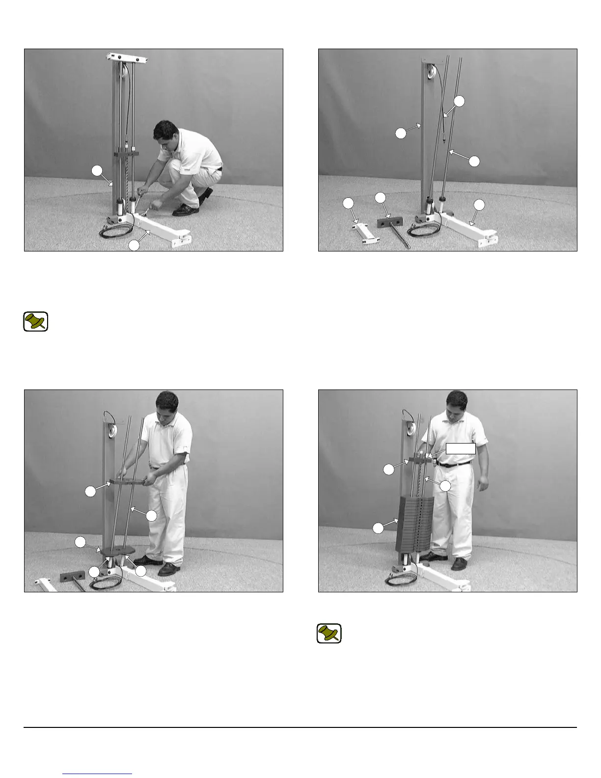
FIG. 1 On a flat surface, attach the Bottom Cross Brace (#38) to
the assembled Weight Stack Frame (#1), in the position as shown
above, and secure it into place using two Hex Head Cap Screws 1/2-
13 X 3 1/2 (#24), four Flat Washers SAE 1/2” (#29), and two Nylon In-
sert Lock Nuts 1/2-13 (#22).
Note: Use the overhead view on the cover page for designing
your layout before assembling.
FIG. 2 Remove the Guide Rod Retainer (#5), and the Top Plate
Selector Bar (#9) to allow the assembly of the weight plates.
Owner’s Manual: Assembly Instructions
2
SP-403 Multi-Press
38
1
4
1
38
87
8
4
8
15
15
FIG. 3 Carefully begin sliding the Weight Plates (#8) onto the
Guide Rods (#4), in position as shown above, allowing the first one
to rest on top of the Rubber Donuts (#15).
FIG. 4 Slide the Top Plate Selector Bar (#9) onto the Guide
Rods (#4) allowing it to rest on top of the completed Weight Stack.
Note: Be sure the label on the Top Plate Selector Bar (#9) is
facing out, as shown above, before sliding the Top Plate Se-
lector Bar (#9) onto the Guide Rods (#4).
9
4
8
Label
9
5