EasyManua.ls Logo

Tundra M1500 - User Manual

Tundra M1500
27 pages
Print Icon
To Next Page IconTo Next Page
Loading...
Quick troubleshooting Guide
TUN-QTSG-0519-EN_A3
For power inverter models M1500 – M2000 – M2500 – M3000
ANNEX 3
Tel.: 450.649.2470 / 1.877.964.2582 Fax.: 1.888.855.9834
TUNDRAINVERTERS.COM
INSTALLATION WORKBOOK
POWER INVERTER SYSTEM / SLEEPER TRUCKS
MODELS: M1500 – M2000 – M2500 – M3000
TUNDRA INTERNATIONAL
ALL RIGHTS RESERVED
All rights reserved. No part of this publication may be reproduced or used without the prior written
permission of Tundra International. No liability can be accepted for any inaccuracies or omissions in
this publication, although every possible care has been taken to make it as complete and accurate as
possible. The right is reserved to make changes at any time without prior notice, and without incurring
an obligation to make such changes applicable to previously manufactured products. All information
contained in this publication is based on the latest product information available at the time of
publication. Illustrations and photographs in this publication are intended for reference use only.
© ALL RIGHTS RESERVED
APRIL 2017
Part No. TDIW-0417-EN
First Edition
PRINTED IN CANADA
1

Other manuals for Tundra M1500

Question and Answer IconNeed help?

Do you have a question about the Tundra M1500 and is the answer not in the manual?

Summary

General Information

Foreword

Introduction to the manual's purpose and required user expertise for installation.

Safety First

Essential safety recommendations for inverter installation and operation to prevent injury.

Limitations

Disclaimer regarding electrical codes, liability, and product specifications subject to change.

Presentation

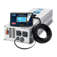
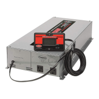
Overview of the Tundra power inverter system, its key features, and benefits.

Parts Listing

Identification of components for the power inverter and the CM installation kit.

Installation - Inside the Cab

Danger - High Voltage

Critical warning about the lethal electrical current produced by the power inverter.

Think Quality

Emphasizes meticulous work and precise measurements for reliable installation results.

Where to Install the Inverter

Specifies mandatory installation location inside the cab, avoiding restricted areas.

Ventilation

Guidelines for maintaining adequate clearance for proper inverter heat dissipation.

Determining the Best Location

Steps to select the optimal installation spot using the provided template and kit.

Validating Your Location Choice

Criteria to check before drilling to prevent damage to under-cab components.

Floor Adapters - Pilot Holes

Instructions for drilling two 1/8" pilot holes to validate the chosen location.

Floor Adapters - Hole Saw Drilling

Procedures for drilling main holes for floor adapters using appropriate hole saw sizes.

Floor Adapters - Installation

Step-by-step guide to install floor adapters and secure cables through the floor.

Power Inverter - Installation

Instructions for physically mounting the power inverter unit to the vehicle chassis.

Connecting the 12 V Cables to the Power Inverter

Connecting positive and negative cables with insulators and bolts to the inverter's DC inputs.

Connecting the 12 V Cables to the Power Inverter (contd)

Adjusts, secures, and routes cables under the cab using loom and ties for protection.

Grounding Verification

Method to test and confirm the power inverter's housing is properly grounded to the chassis.

Grounding Procedure (if required)

Steps to establish a ground connection from the inverter to the vehicle chassis.

Multidata LCD Monitor - Best Location

Criteria for selecting the ideal placement for the Multidata LCD monitor.

Multidata LCD Monitor - Recessed Installation

Detailed instructions for flush-mounting the Multidata LCD monitor into a vehicle panel.

Multidata LCD Monitor - Recessed Installation (contd)

Continues recessed installation, covering measurements and protective measures during cutting.

Multidata LCD Monitor - Surface Installation

Steps for mounting the Multidata LCD monitor onto a surface using its dedicated kit.

Multidata LCD Monitor - Surface Installation (contd)

Finalizes surface mounting by connecting the cable and attaching the monitor with screws.

Installation - Under the Cab

Cable Protection

How to protect cables under the cab from road debris and damage using loom and ties.

Cable Routing

Instructions for properly routing power inverter cables to the battery box and securing them.

Cable Routing (contd)

Creating cable loops for suspension movement and securing them to prevent vibration.

Batteries - Fuse Holder Installation

Procedure for installing the fuse holder and connecting the positive battery cable.

Batteries - Connecting Cables

Steps for connecting power inverter cables to batteries, ensuring correct polarity and placement.

Batteries - Securing Cables

How to attach power inverter cables to other cables on top of batteries for safety and organization.

Overview

The Tundra International truck power inverter system is a battery-powered electrical system designed to provide 120 volts AC power, similar to that found in conventional power grids. When connected to a battery bank, it generates sufficient power for the driver to operate various electrical and electronic devices. This system incorporates state-of-the-art technologies, making it one of the most sophisticated and reliable in the industry, promising years of trouble-free operation.

Key Features:

  • State-of-the-art microprocessor: Ensures efficient and precise control over the inverter's operations.
  • High-capacity components: Designed for a superior service life, contributing to the system's durability and reliability.
  • Multidata LCD display: Allows users to track energy consumption and assists in resolving potential problems by providing real-time data.
  • Ultralight one-piece design: Engineered to withstand strain, vibrations, and impacts, making it suitable for the demanding environment of a truck.
  • Aeronautical-grade assembly: Reflects a high standard of construction, ensuring robust performance.

Key Benefits:

  • Outstanding efficiency and ultra-precise performance levels: Maintains optimal operation at all times.
  • Extends the life cycle of the truck's electrical charging and starting systems: By providing a stable power source, it reduces stress on the truck's existing electrical infrastructure.
  • Lowest cost of ownership: Claimed to be up to 2½ times less than the competition, highlighting its economic advantage over time.

Important Technical Specifications (for models M1500 – M2000 – M2500 – M3000):

  • Power output: Provides 120 volts AC power.
  • DC input: Requires 12 V DC input from a battery bank.
  • Mounting holes: Specific dimensions for mounting holes are provided in the CM installation kit template (e.g., 1/8" pilot holes, 9/32" for mounting bolts).
  • Floor adapter hole sizes: Vary depending on the CM installation kit:
    • 7/8" for CM1512 / CM1510 / CM1508 / CM1506 models.
    • 1 1/8" for CM2012 / CM2010 / CM2008 / CM2006, CM2512 / CM2510 / CM2508 / CM2506, CM3012 / CM3010 / CM3008 / CM3006 models.
  • Monitor cable length: The multidata LCD monitor cable measures 20 ft. (6 m).
  • Maximum tightening torque for DC inputs: 20 lb-ft.
  • Grounding wire: An 8 AWG wire with terminals is recommended for grounding.

Usage Features:

  • Installation location: The power inverter MUST be installed inside the cab, specifically in the luggage compartment under the bed, either flat on the floor or on a vertical steel wall. It should NEVER be installed in a cabinet, in the boots storage, or behind the seat.
  • Ventilation: Despite producing very little heat, a minimum clearance of 7 cm (2") at the ends of the inverter is required for proper ventilation.
  • Multidata LCD monitor: Can be installed either recessed or surface-mounted, allowing flexibility based on cab design and user preference. The monitor provides critical information for tracking energy consumption and troubleshooting.
  • Cable routing: Cables must be routed carefully to the battery box, secured with metallic clips and self-drilling screws, and protected with plastic loom. A "loop" must be made near the battery box to compensate for cab suspension movement.
  • Battery connections: Cables must be connected to the batteries to distribute the charge evenly among all batteries. Positive and negative cables should be kept as far apart as possible. A maximum of three terminals per battery post is allowed. Power inverter cables must be placed above interconnectors.
  • Fuse holder installation: The fuse included in the CM installation kit must be installed in the fuse holder, with specific tightening torques for the nuts (10 lb-ft).
  • Power inverter switch: The switch on the front panel of the power inverter must be OFF before connecting cables to the batteries.

Maintenance Features:

  • Grounding verification: A test lamp can be used to verify adequate grounding by connecting a 12 V power source to the grounding bolt on the back panel of the inverter. If the lamp illuminates, grounding is sufficient.
  • Grounding procedure (if required): If grounding is not adequate, an 8 AWG wire should be used to connect the GROUND terminal on the back panel of the inverter to a metallic part of the vehicle chassis. It is crucial NOT to connect the GROUND terminal to the negative input terminal of the power inverter.
  • Cable protection: All cables under the cab should be covered with the provided plastic loom to protect them from road debris and extend their integrity. Cables should be secured with plastic ties every 12 inches to prevent vibration.
  • Battery post care: It is advised never to apply greasy "protective" products on battery posts, as these can attract contaminants, interfere with connections, and discharge batteries. A liquid protective product that dries completely should be used instead.
  • Cable management: Excess cable should not be cut but wound on top of the batteries and secured with plastic ties to the other cables. This helps distribute weight and limit stress on the ties.
  • Quality installation: The manual emphasizes "THINK QUALITY, MEASURE TWICE, CUT ONCE" to ensure a successful installation and avoid costly mistakes. It recommends reading instructions thoroughly, keeping the work area clean, and using specified tools. If the owner lacks sufficient experience, installation should be performed by a qualified technician.
  • Safety warnings: The manual highlights the danger of high voltage and the potential for severe injury or death if the inverter is not handled properly. It also warns against reversing polarity during DC input connections and advises caution around sharp edges and exhaust pipes when routing cables.

Tundra M1500 Specifications

General IconGeneral
BrandTundra
ModelM1500
CategoryInverter
LanguageEnglish

Related product manuals