U s e A n d M a i n t e n a n c e I n s t r u c t i o n s
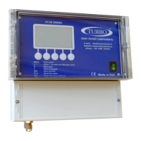
E conomizer E8T 16 Output Channel s
I n Mn E E8 T
e n R ev . 0 0
T UR B O S rl
D u s t F i l t e r C o m p o n en t s
V i a P o 3 3 / 3 5 2 0 8 11 C e s an o M a d e r n o ( M B ) I t a l y T e l + + 3 9 0 3 6 2 5 7 4 02 4 F a x + + 3 9 0 3 6 2 5 7 4 0 9 2
7
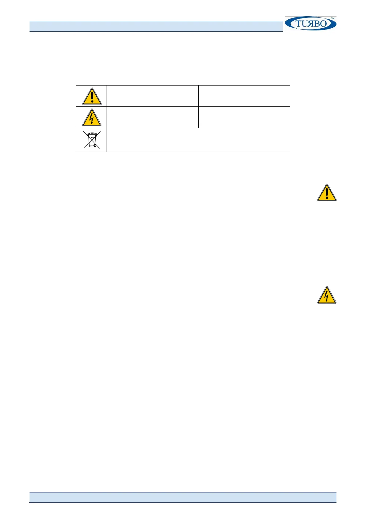
Warning Symbols Used In This Manual
The safety-related indications are highlighted using the symbols:
Attention - Danger
Warning - Generic
Risk – Danger Electric Current
Dispose of in compliance with the electrical and
electronic equipment Standard WEEE
Installation Regulations and Warnings
Protect the equipment from direct exposure to sunlight.
Do not position the equipment near or directly in contact with sources of
heat or electromagnetic fields.
Fix the equipment at a height of at least 60 cm from the ground.
In a clearly visible place that is easily accessible.
Connect the equipment to power lines other than those used for operating motors
or other high power devices, which could generate network interference or
instability.
The unit electric power supply must be protected by a 230Vac~ 30mA Residual
Current Device RCD and a bipolar 230Vac~ 10A magnet circuit breaker, positioned
in a place that is easily accessible.
Before intervening on the equipment to perform any operation, deactivate
the magnet circuit breaker switch.
For electric operations, always remove voltage, wait 30 seconds for the
internal capacitors to discharge before opening. At the end of the
operations, close the equipment before powering up.
Before intervening on the equipment to perform any operation, check the
conditions of the atmosphere are safe.
For connection of the supply voltage, use flame-retardant wires with a minimum
section of 0.75mm² certified and conform to the IEC 60227 or IEC 60245
standard.
Use flame-retardant cables with a minimum cross-section area of 0.75 mm² for all
control signals.
Use flame-retardant cables with a minimum cross-section area of 0.75 mm² to
connect to the indicating relays.
The earth wire must be yellow/green.
The earth wire must be connected first.
The yellow/green wire must only be used for the earth connection.