EasyManua.ls Logo

Turbosmart E-Boost Street 40PSI User Manual

Turbosmart E-Boost Street 40PSI
20 pages
To Next Page IconTo Next Page
Page #1 background imageLoading...
Page #1 background image
1
------------------------------------------------------------------------------------------------------------------------
BEFORE YOU START IMPORTANT NOTES
Turbosmart recommends that your E-Boost Street is fitted by an appropriately qualified technician.
Consult your local tuning specialist before setting your boost pressure as setting boost beyond your engines capability can result in
severe engine damage or failure
Turbosmart recommends that the engines Air/Fuel ratio is checked once the desired boost pressure is set. Any increase in boost
pressure can cause the engine to run lean resulting in severe engine damage or failure
Turbosmart recommends that the E-Boost Street is not used in conjunction with any type of “Draw Through” induction System.
Turbosmart recommends that boost pressure is set using a Dynamometer and not on public roads.
The E-Boost Street may not be able to completely compensate for a drop in boost pressure at high RPM due to the turbocharger
operating beyond its maximum efficiency range i.e. incorrect turbocharger sizing or excessive exhaust backpressure.
The E-Boost Street cannot compensate for increases in boost pressure at high RPM due to inadequate waste gate flow capacity;
the turbo system must maintain a steady base boost curve before you start using a boost controller.
The E-Boost Street cannot be used with external waste gates that are in a poor, worn or non-serviceable condition.
For best results your turbocharger should be correctly sized for your application.
Erratic operation of electronic parts can be caused by Electro Magnetic Interference (EMI). EMI can be generated by aftermarket
ignition systems such as CDI which, if wired incorrectly, generate large amounts of EMI through the vehicles electrical system. This
can cause items such as ECU’s and boost controllers to be effected. Please follow ignition system installation instructions VERY
carefully to avoid EMI affecting the E-Boost Street. Sometimes, using resistor type spark plugs can reduce this problem.
The E-Boost Street is not waterproof and must be mounted inside the cabin. The unit has an operating temperature range of -5
O
C
to 70
O
C.
Document Type: Instruction Manual
Product Name: E-Boost Street 40PSI
Product Description: Electronic boost controller
Product Number: TS-0302-1002

Table of Contents

Question and Answer IconNeed help?

Do you have a question about the Turbosmart E-Boost Street 40PSI and is the answer not in the manual?

Turbosmart E-Boost Street 40PSI Specifications

General IconGeneral
Max Boost Pressure40 PSI
TypeElectronic Boost Controller
DisplayYes
Control TypeElectronic
Input Voltage12V
Solenoid IncludedYes
Display TypeLCD
CompatibilityUniversal
Warranty1 Year

Summary

Pre-Installation Guidelines

Important Notes Before Installation

Crucial safety and operational guidelines to follow before fitting the E-Boost Street for optimal performance and safety.

Installation Guide

Wiring and Signal Connections

Details the electrical wiring and RPM signal input for the E-Boost Street unit.

Solenoid Mounting

Provides guidance on how to properly mount the E-Boost Street solenoid.

Solenoid Hook Up Methods

Internal Wastegate Connections

Illustrates connection methods for internal wastegate setups.

External Wastegate Connections

Illustrates connection methods for external wastegate setups.

Basic Functionality

Unit Layout and Operation Modes

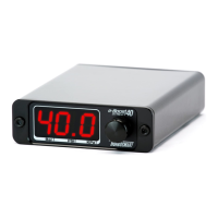
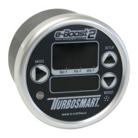
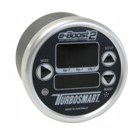
Details the unit's physical layout, OFF mode, and live display modes.

Boost Group Switching

Describes how to switch between the two programmable boost groups (SP1/SP2).

Setup Menu Introduction

Accessing and Navigating Setup

Instructions on how to enter and navigate the setup menu using the knob.

Over Boost Shutdown (OBS)

Configuration for an over-boost protection feature to prevent engine damage.

Scale Configuration (SCL)

Allows setting the display units for boost pressure (Bar, PSI, KPa).

Boost Control Setup

Boost Group 1 & 2 Configuration

Configures boost set point, gate pressure, and sensitivity for two groups.

Setting Boost Set Point (SP)

Procedure for setting the desired boost pressure level for a boost group.

Setting Gate Pressure (GP)

Adjusting gate pressure to improve boost response and torque at lower RPM.

Advanced Setup Options

Setting Sensitivity (SN)

Fine-tuning boost curve sensitivity to address wavy or dropping boost.

RPM Signal and Switch Logic

Configuring RPM signal input and switch logic for boost group selection.

Auxiliary Output Control

Controlling auxiliary devices like water spray or shift lights based on boost or RPM.

Further Setup Functions

Boost Correction Function

Setting up boost correction to prevent high RPM boost drop-off.

Security Pin Configuration

Establishing a password to lock configuration parameters and prevent tampering.

RPM Shift Light and Zero Display

Configuring shift lights and calibrating the zero display reading.

Solenoid, Reset, and Troubleshooting

Solenoid Cycle and Factory Reset

Tests solenoid connection and restores settings to factory defaults.

Troubleshooting Common Issues

Addresses over-boosting, under-boosting, and fluctuating boost pressure problems.

Basic Functionality Details

Unit Layout and Indicators

Diagram and explanation of the E-Boost Street unit's physical components and indicators.

Operating Modes

Description of OFF mode and the different Live mode display options.

Boost Group Switching

Procedure for switching between the two programmable boost groups (SP1/SP2).

Setup Menu Navigation

Accessing Setup Parameters

Instructions on how to enter and navigate the setup menu using the knob.

Key Setup Parameter Overview

Overview of essential setup parameters like OBS, Scale, Boost Setup, RPM Config, COR, PIN.

Over Boost Shutdown & Scale Setup

Over Boost Shutdown (OBS) Configuration

Detailed setup for engine protection against over-boosting.

Scale (SCL) Unit Selection

Allows setting the display units for boost pressure (Bar, PSI, KPa).

Boost Setup Parameters

Setting Boost Set Point (SP)

Procedure for setting the desired boost pressure level for a boost group.

Setting Gate Pressure (GP)

Adjusting gate pressure to improve boost response and torque at lower RPM.

Setting Sensitivity (SN)

Fine-tuning boost curve sensitivity to address wavy or dropping boost.

Advanced Setup Functions

RPM Signal and Switch Logic

Configuring RPM signal input and switch logic for boost group selection.

Auxiliary Output and Boost Correction

Controlling auxiliary devices and setting up boost correction for high RPM.

Security and Display Settings

Security Pin Configuration

Establishing a password to lock configuration parameters and prevent tampering.

RPM Shift Light and Zero Display

Configuring shift lights and calibrating the zero display reading.

Solenoid, Reset, and Troubleshooting

Solenoid Cycle and Factory Reset

Tests solenoid connection and restores settings to factory defaults.

Troubleshooting Common Issues

Addresses over-boosting, under-boosting, and fluctuating boost pressure problems.

Product Warranty and Pledge

One Year Limited Warranty

Details the warranty terms, conditions, and coverage for Turbosmart products.

Turbosmart Pledge and Agreement

Customer agreement outlining responsibilities, warranty claims, and product usage.

Related product manuals