user manual
LMS-D6
LMS-D6 user manual
Page 8
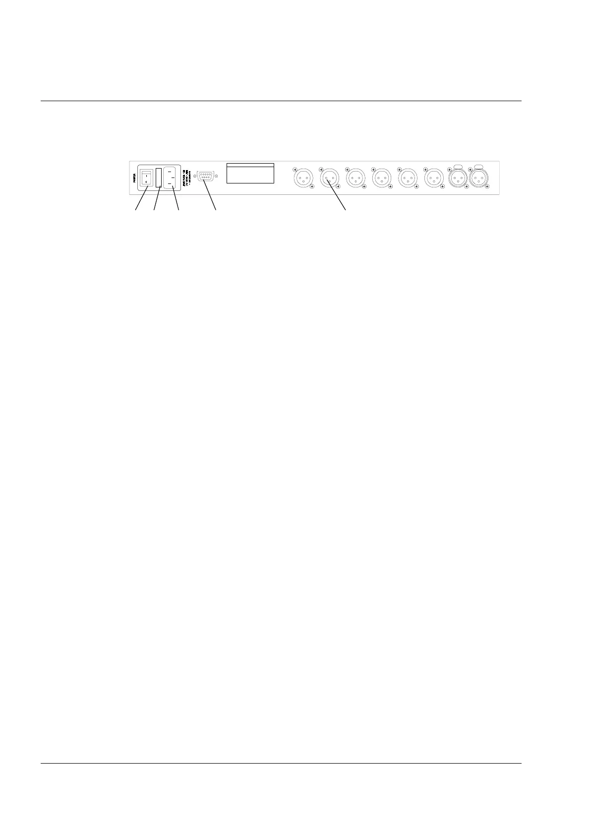
Rear Panel Functions
1. Power Switch.
2. Mains Fuse - Located in a finger-proof fuseholder adjacent to the mains inlet. Always replace
this fuse with the correct type as shown on the rear panel legend. (N.B. A spare fuse is located
in this holder.)
3. Mains Power - Connected via a standard IEC socket. A compatible power cord is supplied with
the unit.
4. External - RS232 via a 9-pin DIN DEE socket, for connection to a PC.
5. XLR Inputs and Outputs - 3 pin XLR connectors are provided for each audio input and output.
All terminations are fully balanced, pin 2 Hot, pin 3 Cold and pin 1 Screen (shield).
1 2 3 4 5
INPUT B INPUT A
CUSTOM MADE FOR TURBO SOUND
IN THE UK BY XTA ELECT RONICS
PROTECTION AGAINST FIRE
REPLACE ONLY WITH THE
SAME TYPE T1A, 250V FUSE
RS232
DATA IN P UT
PIN1=SHIELD
PI N2=HOT
PIN3=COLD
THIS EQUIPMENT MU ST BE EARTHED
RISQ UE DE CHOC E LECT RIQUE - NE PA S OUVR IR
WARNING / AVIS
TP
T
TP
T
TP
T 4
TP
T
TP
T 2
TP
T 1
DO NOT EXPOSE TO RAIN OR MOISTURE
SHOCK HAZARD – DO NOT REMOVE COVERS
 Loading...