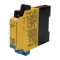
4.5.2 Hardware architecture
The device is considered as a Type A component (non complex). The hardware fault tolerance HFT is 0.
4.5.3 Characteristic values for IM33-… isolating transducers
The device can be used for applications up to SIL 2.
MTBF = MTTF + MTTR = 1/(λ
total
+ λ
not part
) + 8 h = 159 years
Fail-safe state = fail high
Failure category λ
sd
λ
su
λ
dd
λ
du
SFF DC
S
2
DC
D
2
λ
low
= λ
sd
λ
high
=
λ
dd
233 FIT 315 FIT 73 FIT 44 FIT 93 % 42 % 62 %
λ
low
= λ
dd
λ
high
=
λ
sd
73 FIT 315 FIT 233 FIT 44 FIT 93 % 18 % 84 %
Fail-safe state = fail low
Failure category λ
sd
λ
su
λ
dd
λ
du
SFF DC
S
2
DC
D
2
λ
low
= λ
sd
λ
high
=
λ
dd
239 FIT 315 FIT 67 FIT 44 FIT 93 % 43 % 60 %
λ
low
= λ
dd
λ
high
=
λ
sd
67 FIT 315 FIT 239 FIT 44 FIT 93 % 17 % 84 %
IM33-… – Average probability of failure on demand
T[Proof] = 1 year T[Proof] = 5 years T[Proof] = 10 years
PFD
AVG
= 1.92 × 10
-4
PFD
AVG
= 9.60 × 10
-4
PFD
AVG
= 1.92 × 10
-3
NOTE
The PFD
AVG
value of the isolating transducers should be designed to be max. 10% of the total permissible PFD
AVG
value for the safety integrity level SIL2. A PFD
AVG
value marked in green means that the PFD value is within the
range of SIL2 in accordance with IEC 61508-1 and is less than 10% of the total value for SIL2. A PFD
AVG
value
marked in yellow indicates that the PFD value is within the range of SIL2 in accordance with IEC 61508-1 but is
more than 10% of the total value for SIL2.
4.6 Recurrent function tests
A function test must be completed prior to initial operation, after each parameter setting, after repair and replace-
ment, as well as at the stipulated interval T[Proof]:
Ensure that the function test is only carried out by qualified personnel.
Think first about your safety and the safety of your environment. If in doubt, replace the device.
Bridge the isolating transducer in the safety controller (process control system) and ensure that safety is main-
tained. You as the operator are responsible for ensuring that safety is maintained.
Check the transmission behavior of the device with a suitable transducer and measuring device in 1 mA steps.
With intrinsically safe device variants follow the regulations for Ex protection.
If all checks have been completed and no faults found, restart the safety circuit.
Once the test has been completed, document and archive the results.
NOTE
The function test detects more than 90% of the undetected dangerous failures (Du) of the device
4.7 Useful life
The calculated failure rates of the device are valid for a useful lifetime of 8 years.

 Loading...