more@turck.com • www.turck.com • 2015/04
Decommissioning and withdrawal from service
© exida.com GmbH TURCK 04-07-14 R001 V2R0.doc; February 8, 2013
Stephan Aschenbrenner Page 15 of 25
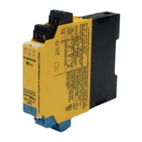
5.1 Isolating Transducers IM33-**(Ex)-Hi/24VDC
The FMEDA carried out on the Isolating Transducer IM33-22Ex-Hi/24VDC leads under the
assumptions described in sections 4.2.3 and 5 to the following failure rates:
λ
sd
= 0,00E-00 1/h
λ
su
= 6,00E-09 1/h
λ
dd
= 0,00E-00 1/h
λ
du
= 4,39E-08 1/h
λ
high
= 6,71E-08 1/h
λ
low
= 2,33E-07 1/h
λ
no effect
= 3,15E-07 1/h
λ
total
= 6,65E-07 1/h
λ
not part
= 5,28E-08 1/h
MTBF = MTTF + MTTR = 1 / (λ
total
+ λ
not part
) + 8 h = 159 years
These failure rates can be turned over into the following typical failure rates:
Failure category (Failure rates in FIT)
Fail-safe state =
“fail high”
Fail-safe state =
“fail low”
Fail High (detected by the logic solver) 73
Fail detected (int. diag.) = λ
sd
+ λ
su
6
+ λ
dd
6
Fail high (inherently) = λ
high
67
Fail Low (detected by the logic solver)
233
Fail detected (int. diag.) = λ
sd
+ λ
su
+ λ
dd
6
Fail low (inherently) = λ
low
233
Fail Dangerous Undetected 44
MTBF = MTTF + MTTR 159 years
Under the assumptions described in section 4.2.4 and 5 the following tables show the failure
rates according to IEC 61508 depending on whether fail low / fail high was considered to be
dangerous detected or safe detected to:
6
These failures are not detected by internal diagnostics but because they lead to the safe state (e.g. by
reaching the user defined trip point) they are detected by the logic solver independent of the user defined
fail-safe state (“fail low” or “fail high”).

 Loading...