© exida.com GmbH TURCK 04-07-14 R001 V2R0.doc; February 8, 2013
Stephan Aschenbrenner Page 2 of 4
Management summary
This report summarizes the results of the hardware assessment carried out on the Isolating
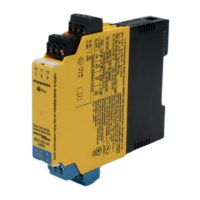
Transducers IM33-**(Ex)-Hi/24VDC and Analog Signal Transmitters IM35-**Ex-Hi/24VDC.
Table 1 gives an overview of the different versions that belong to the considered devices.
The hardware assessment consists of a Failure Modes, Effects and Diagnostics Analysis
(FMEDA). A FMEDA is one of the steps taken to achieve functional safety assessment of a
device per IEC 61508. From the FMEDA, failure rates are determined and consequently the
Safe Failure Fraction (SFF) is calculated for the device. For full assessment purposes all
requirements of IEC 61508 must be considered.
Table 1: Version overview
Type Description Parts List / Circuit Diagram
IM33-11Ex-Hi/24VDC
IM33-11-Hi/24VDC
1 input / 1 output 12260705 /
2260700 Ind. A of 28.06.04
IM33-12Ex-Hi/24VDC 1 input / 2 outputs 12260704 and 12263704 /
12260700 Ind. A of 28.06.04
IM33-22Ex-Hi/24VDC
IM33-22-Hi/24VDC
2 inputs / 2 outputs 12260703 and 12263703 /
12260700 Ind. A of 28.06.04
IM35-11Ex-Hi/24VDC 1 input / 1 output 12280003 /
12280000 Ind. – of 17.10.03
IM35-22Ex-Hi/24VDC 2 inputs / 2 outputs 12280001 and 12280101 /
12280000 Ind. – of 17.10.03
The failure rates used in this analysis are the basic failure rates from the Siemens standard
SN 29500.
According to table 2 of IEC 61508-1 the average PFD for systems operating in low demand
mode has to be ≥10
-3
to < 10
-2
for SIL 2 safety functions. However, as the modules under
consideration are only one part of an entire safety function they should not claim more than
10% of this range, i.e. they should be better than or equal to 1,00E-03.
The Isolating Transducers IM33-**(Ex)-Hi/24VDC and Analog Signal Transmitters
IM35-**Ex-Hi/24VDC are considered to be Type A
1
components with a hardware fault tolerance
of 0.
For Type A components the SFF has to be 60% to < 90% according to table 2 of IEC 61508-2
for SIL 2 (sub-) systems with a hardware fault tolerance of 0.
Assuming that a connected safety logic solver to the Isolating Transducers
IM33-**(Ex)-Hi/24VDC can detect both over-range (fail high) and under-range (fail low), high
and low failures can be classified as safe detected failures or dangerous detected failures
depending on the application (see section 4.2.4). The following tables show how the above
stated requirements are fulfilled based on the different applications.
1
Type A component: “Non-complex” component (all failure modes are well defined); for details see
7.4.3.1.2 of IEC 61508-2.

 Loading...