11
TP9KF
July 2015-A
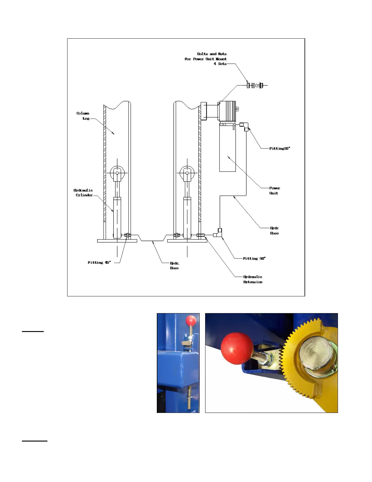
Hose Route Diagram
Fig. 18
Fig. 16
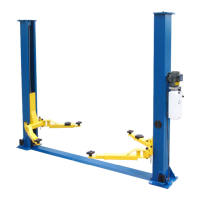
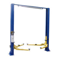
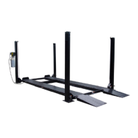
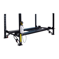
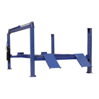
STEP 9: (Installing Lifting Arms & Arm Restraints)
Install the lifting swing arms on the
carriages using the included 1-1/2”
diameter pins. Check for proper
engagement of the arm restraint. The
rack on the arm restraints should fully
engage the gear on the arm (Figs. 17-19).
Fig.17 Fig. 18
STEP 10: Mount Drive-Over Base Plate at this time, using bolts provided (Fig 9 & 19).
 Loading...