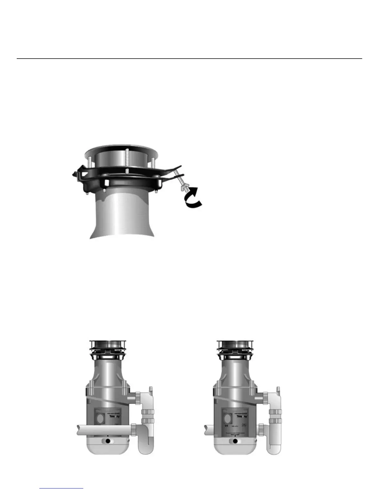
4. Swing the unit up into position and tighten the wing nut.
5. Slightly rotate the disposer as necessary on the circlip until the elbow is in correct alignment
with the drainage fi ttings.
6. Mark position of the suspension plate relative to the sink and remove the disposer.
7. Tighten up the four allen screws in the suspension plate.
8. Replace the splash-guard in the top of the disposer and lubricate the edges with soap or grease.
9. Re-hang unit on the suspension plate, swing it up, align carefully, and tighten the wing nut.
10. The outlet elbow may now be connected to the drainage system. It is essential to have no
sharp bends, vanes or obstructions in the waste pipe run from the disposer to the soil gully.
38mm bore pipe must be used throughout and there must be no change in section of the
bore due to free bending. The discharge end of the waste pipe must discharge below the grid
of the soil gully to prevent a build up of waste. N.B. The spigot on the outlet bend may be
opened to accommodate the discharge from a dishwasher or sink overfl ow.
An ‘S’ or ‘P’ type trap must be used. A bottle trap must not be used.
11. Ensure that there are no foreign objects in the grind chamber, fi ll the sink with water, remove
plug. Check for leaks. Always ensure there is an adequate supply of water fl owing through
the unit when switched on.
No Ye s
9