MODBUS function code 0x10: write multiple registers
This function code is used to write continuous registers to remote devices (1... 123 registers) block
that specifies the value of the registers written in the request data frame. Data is packaged in two
bytes per register. Response frame return function code, start address and number of registers
written.
Request
N = Register number
Figure11:Write multiple register request frames
Response
N = Register number
Figure 12: write multiple register response frames
The request frame and response frame are illustrated below in two registers that write the values
0x000A and 0x0102 to the start address of 2.
15
Function code
Start Address
Number of input registers
number of bytes
Register values
1 byte
2 byte
2 byte
1 byte
N×2 byte
0x10
2 byte
2 byte
1 byte
N×2 byte
Request Frame
Number Systems
Function code
Start address (high byte)
Start address (low byte)
Input register number (high bytes)
Input register number (low bytes)
number of bytes
Register value (high byte)
Register value (low byte)
Register value (high byte)
Register value (low byte)
(Hexadecimal)
0x10
0x00
0x01
0x00
0x02
0x04
0x00
0x0A
0x01
0x02
Response Frame
Number Systems
Function code
Start address (high byte)
Start address (low byte)
Input register number (high bytes)
Input register number (low bytes)
(Hexadecimal)
0x10
0x00
0x01
0x00
0x02
Function code
Start Address
Register number
1 byte
2 byte
2 byte
0x10
0x0000….0xffff
1…123(0x7B)
Figure 13: Examples of writing multiple register request and response frames
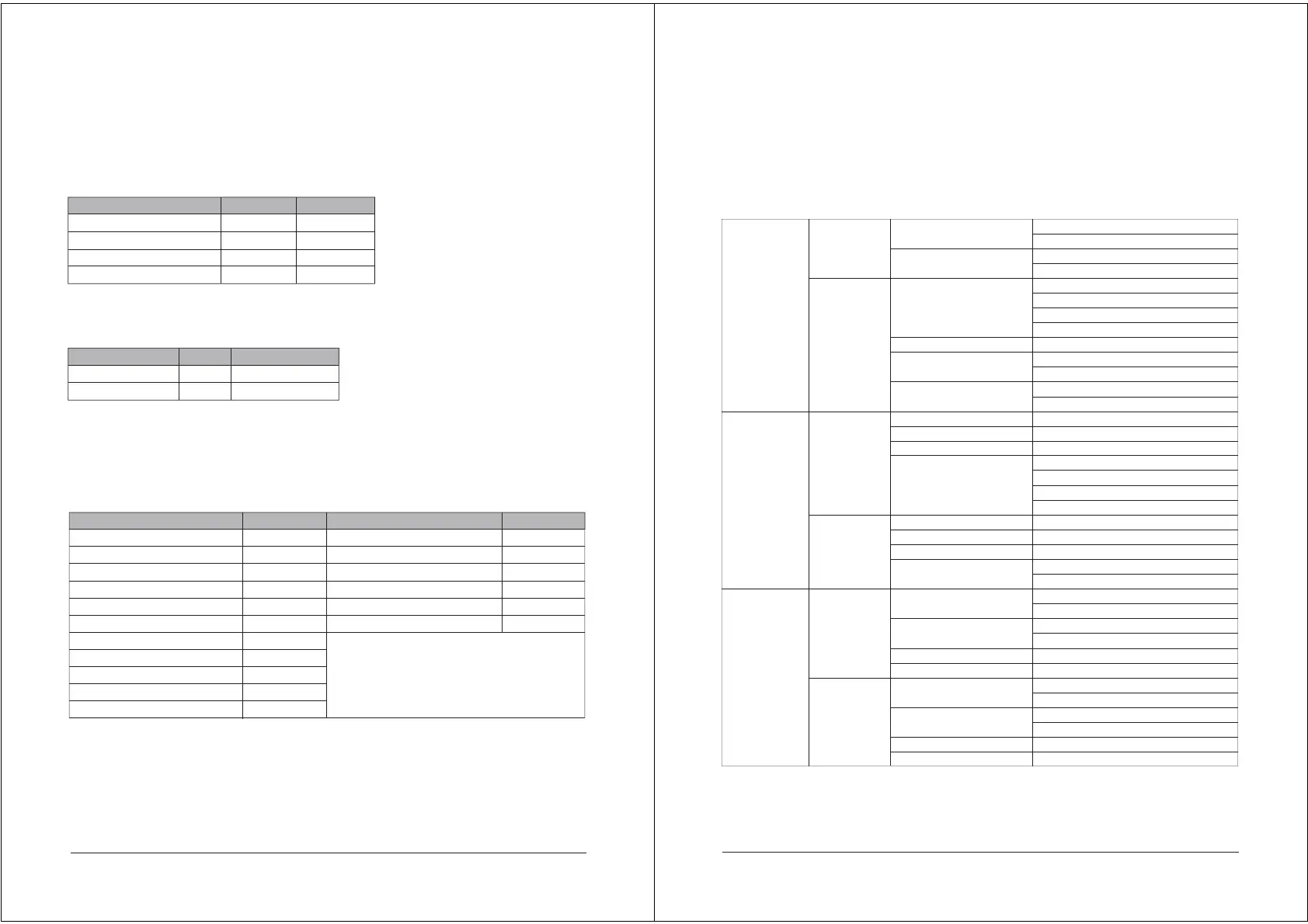
Type
Unit
Temperature Sensor
Temperature Offset
Temperature Input
Temperature Unit
USA:7.00,4.01,10.01
NIST:6.86,4.01,9.18
ORP Standard Sulution
Correction
Field Calibration
Offset1 Adjustment
Slope1 Adjustment
Offset2 Adjustment
Slope2 Adjustment
Status
High/Low Setpoint
Limit Value
Hysteresis
Status
High/Low Setpoint
Limit Value
Hysteresis
Sensor
Temperature
Standard
Calibration
Field
Calibration
Relay 1
Relay 2
Configure
Calibration
Alarm
PH
ORP
pH
mV
NTC2.252 kΩ
NTC10 kΩ
Pt100
Pt1000
0.0000
Automatic
Manual
°C
°F
Automatic identification,calibrate 7.00 first
Automatic identification,calibrate 6.86 first
235mV(Default)
Offset 1
Slope 1
Offset 2
Slope 2
ON
OFF
High Alarm
Low Alarm
ON
OFF
High Alarm
Low Alarm
8
Menu structure
If the monitor prompts you to enter the calibration security password, press the【▼】 key or 【Ӝ】key to
set the calibration security password, and then press the 【ENT】key to confirm the calibration security
password.No initial password here,please enter directly by press【ENT】key.
The following is the menu structure of this instrument,press սMENUվ key to enter menu
setting mode:
 Loading...