9
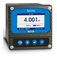
Channel
Output Option
Upper Limit
Lower Limit
Channel
Output Option
Upper Limit
Lower Limit
Baud Rate
Parity Check
Stop Bit
Network Node
Chinese
English
Display Speed
Backlight
Soft Version
Password Settings
Serial Number
1.No
2.Yes
Current 1 4mA
Current 1 20mA
Current 2 4mA
Current 2 20mA
Relay 1
Relay 2
Current 1
Current 2
RS485
Language
Display
Soft Version
Factory Default
Terminal
Current Tuning
Relay Test
Output
System
Main
Temperature
4-20mA
0-20mA
20-4mA
Main
Temperature
4-20mA
0-20mA
20-4mA
4800BPS
9600BPS
19200BPS
None
Odd
Even
1 Bit
2 Bit
Low
Standard
Medium
High
Saving
Bright
19-1.0
0000
(The positive and negative ends
of the ammeter are connected
to the current 1 or current 2
output terminals of the instrument
respectively, press սӞվkey to
adjust the current to 4 mA or
20mA ,pressսENTվkey to confirm.)
(Select two relays and hear the
relay switch twice sounds,
indicate the relay is normal.)
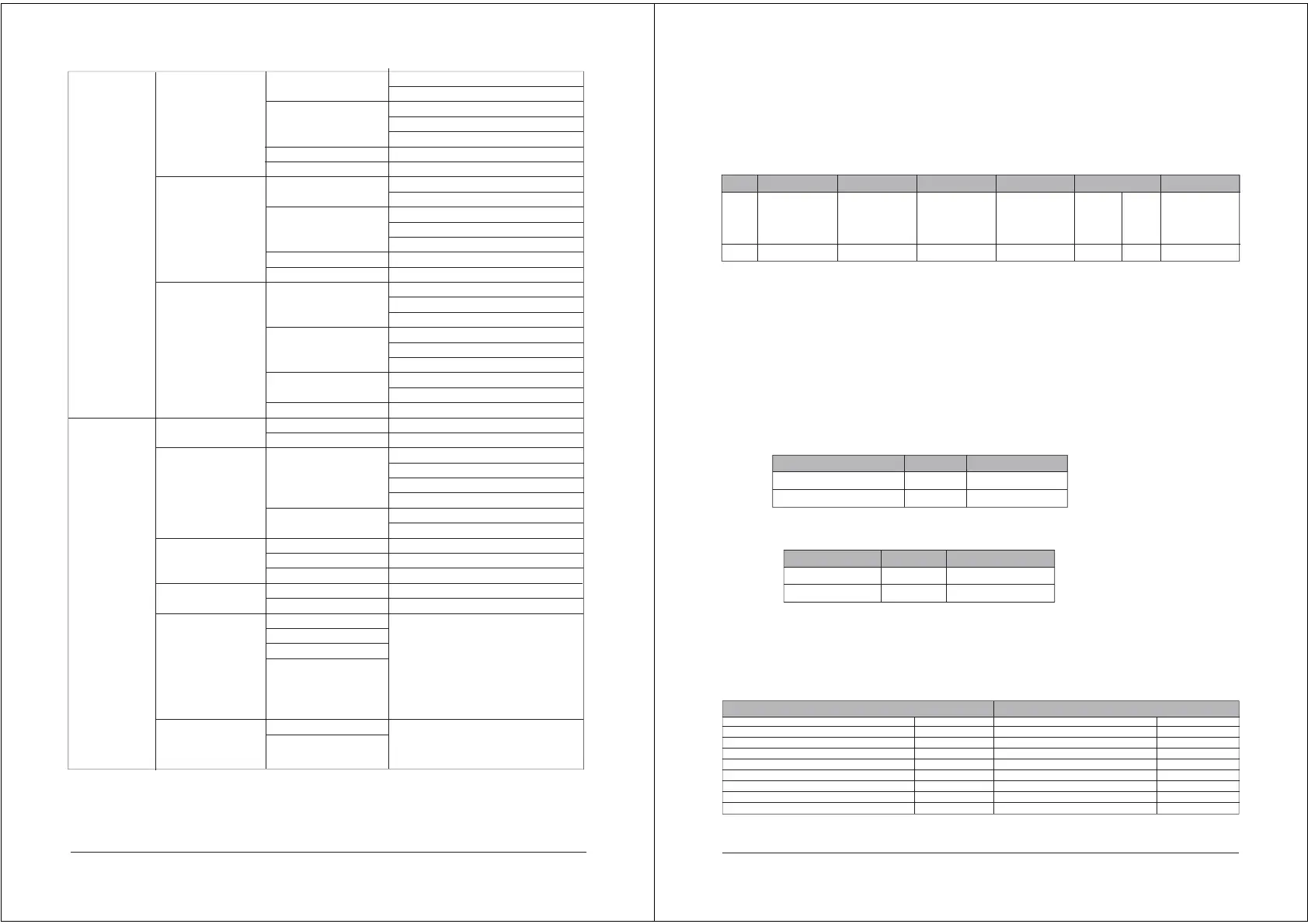
Implementation of MODBUS RTU in Instrument
According to the official MODBUS definition, the command starts with a 3.5 character interval
triggering command, and the end of the command is also represented by a 3.5 character interval.
The device address and MODBUS function code have 8 bits. The data string contains n*8 bits, and the
data string contains the starting address of the register and the number of read/write registers. CRC
check is 16 bits.
Figure 7: MODBUS definition of data transmission
Instrument MODBUS RTU function code
The instrument only uses two MODBUS function codes:
0x03: Read-and-hold register
0x10: Write multiple registers
MODBUS Function Code 0x03: Read-and-hold Register
This function code is used to read the continuous block content of the holding register of the remote
device. Request the PDU to specify the start register address and the number of registers. Address
registers from zero. Therefore, the addressing register 1-16 is 0-15. The register data in the response
information is packaged in two bytes per register. For each register, the first byte contains high bits and
the second byte contains low bits.
Request
Figure 8: Read-and-hold register request frame
Response
N = Register number
Figure 9: Read-and-hold register response frame
The following illustrates the request frame and response frame with the read and hold register 108-110
as an example. (The contents of register 108 are read-only, with two byte values of 0X022B, and the
contents of register 109-110 are 0X0000 and 0X0064)
14
Value
Byte
Start
No signal bytes
during 3.5
characters
3.5
Device address
1-247
1
Function
Function codes
conforming to
MODBUS
specification
1
Data
Data conforming
to MODBUS
specification
n
Summary Check
CRCL
1
End
No signal
bytes during
3.5 characters
3.5
CRCL
1
Function code
Start Address
Read register number
1 byte
2 byte
2 byte
0x03
0x0000….0xfffff
1…125
Function code
number of bytes
Register values
1 byte
1 byte
N×2 byte
0x03
N×2
Request Frame
Number Systems
Function code
Start address (high byte)
Start address (low byte)
Number of Read Registers (High Bytes)
Number of Read Registers (Low Bytes)
(Hexadecimal)
0x03
0x06
0x02
0x2B
0x00
0x00
0x00
0x64
(Hexadecimal)
0x03
0x00
0x6B
0x00
0x03
Response Frame
Number Systems
Function code
Byte count
Register Value (High Bytes) (108)
Register Value (Low Bytes)(108)
Register Value (High Bytes) (109)
Register Value (Low Bytes) (109)
Register Value (High Bytes)(110)
Register Value (Low Bytes) (110)
Figure 10: Examples of read and hold register request and response frames
 Loading...