MODBUS RTU Transmission Mode
When the instrument uses RTU (Remote Terminal Unit) mode for MODBUS serial communication, each
8-bit byte of information contains two 4-bit hexadecimal characters
. The main advantages of this
mode are greater character density and better data throughput than the ASCII mode with the same
baud rate
. Each message must be transmitted as a continuous string.
The format of each byte in RTU mode (11 bits):
Coding system: 8-bit binary
Each 8-bit byte in a message contains two 4-bit hexadecimal characters (0-9, A-F)
Bits in each byte: 1 starting bit
8 data bits, the first minimum valid bits without parity check bits
2 stop bits
Baud rate: 9600 BPS
How characters are transmitted serially:
Each character or byte is sent in this order (from left to right) the least significant bit (LSB)... Maximum
Significant Bit (MSB)
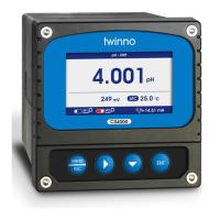
Figure 3: RTU pattern bit sequence
Check Domain Structure: Cyclic Redundancy Check (CRC16)
Structure description:
Figure 4: RTU information structure
The maximum frame size of MODBUS is 256 bytes
MODBUS RTU Information Frame
In RTU mode, message frames are distinguished by idle intervals of at least 3.5 character times, which
are called t3.5 in subsequent sections.
Figure 5: RTU message frame
The entire message frame must be sent in a continuous character stream.
When the pause time interval between two characters exceeds 1.5 characters, the information frame
is considered incomplete and the receiver does not receive the information frame.
MODBUS RTU CRC Check
The RTU mode contains an error-detection domain based on a cyclic redundancy check (CRC)
algorithm that performs on all message contents. The CRC domain checks the contents of the entire
message and performs this check regardless of whether the message has a random parity check. The
CRC domain contains a 16-bit value consisting of two 8-bit bytes. CRC16 check is adopted..Low bytes
precede, high bytes precede.
13
Start bit 1 2 3 4 5 6 7 8 Stop bit Stop bit
Slave Instrument
Address
Function Code
1 byte
Data
0…252 byte
CRC
2 byte
CRC Low byte CRCHigh byte
Starting
≥3.5 characters
Address
8 bit
Function code
8 bit
Data
Nx8 bit
CRC check
16 bit
End
≥3.5 characters
At least 3.5 characters At least 3.5 characters
Frame 1 Frame 2 Frame 3
4.5 characters
3.5 characters
Frame 1 normal
≤1.5 characters >1.5 characters
Frame 2 failure
USA:7.00,4.01,10.01
NIST:6.86,4.01,9.18
ORP Standard Sulution
Field Calibration
Offset Adjustment
Slope Adjustment
Standard
Calibration
Field
Calibration
Calibration
Automatic identification, calibrate 7.00 first
Automatic identification, calibrate 6.86 first
235mV(Default)
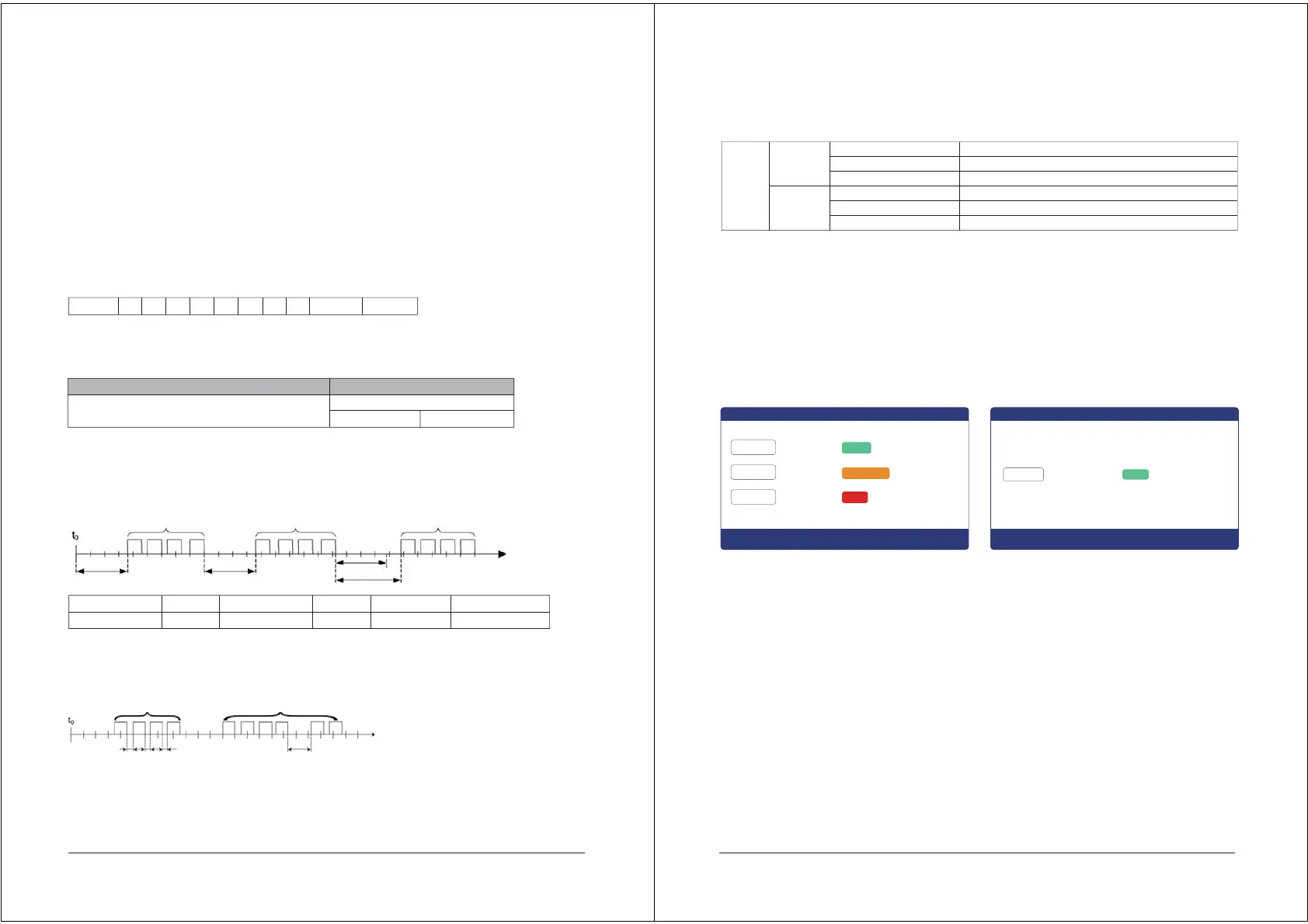
Calibration of Standard Solution
Select the Standard Solution Calibration, a total of two groups: USA: 7.00, 4.01, 10.01 and NIST:
6.86, 4.01, 9.18. After the selection is completed, press the [ENT] button to confirm and enter the
standard sulution calibration mode.
If the instrument has been calibrated, the screen shows the calibration status and then press theս
ENTվ key again to enter the re-calibration if you need re-calibration.
If the monitor prompts you to enter the calibration security password, press theսӞվ key or սӜվkey to set the
calibration security password, and then press the սENTվkey to confirm the calibration security password.
PH Calibration: After entering the calibration mode, the instrument displays as shown above.
The instrument automatically identifies the standard liquid, first calibrates the midpoint (example
7.00pH), then calibrates 4.01pH or 10.01pH. The corresponding mV value will be displayed on the
left side of the screen.
After the calibration is completed, the offset and slope will be displayed on the right side of the
screen.
If only two points of calibration are needed, after two points of calibration, press the սMenuվ
button to exit directly.
During the calibration process, Error prompt appears on the screen when the standard liquid is
wrong.
Calibration results: The slope of glass electrode (> 0.90) is qualified, and that of metal antimony
electrode (> 0.80) is qualified.
Calibration
Press [MENU] to enter the setting mode and select the calibration
PH Calibration ORP Calibration
10
7.00
4.01
10.01
-5 mV
170 mV
-25 mV
0.98
Done
Calibrating
Error
offset:
Slope:
pH / ORP
pH / ORP
235
0.98Done Slope:
228 mV
 Loading...