Field Calibration
Select on-site calibration methods: սLinear calibrationվ, սOffset adjustmentվ, ս
linear
adjustmentվ.
F
ield Calibration
When the data from laboratory or portable instrument are input into this item, the instrument will
automatically correct the data.
Offset adjustment
Compare the data of laboratory or portable instrument with the data of instrument
measurement,if there are errors, the error data can be modified by this function.
Linear adjustment
Linear values after "field calibration" are stored in this item, with factory data of 1.00.
ORP Calibration: Press սMenuվkey to enter the setting mode
, select ORP standard liquid
calibration
, and input the known standard liquid value (default 235mV),press the սENTվ k
ey to
enter the standard solutioncalibration mode
.
If the instrument has been calibrated, the screen shows the calibration status and then press the
սENTվ key again to enter the re-calibration if you need re-calibration.
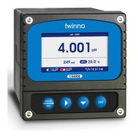
After entering the calibration mode, the instrument will be displayed as the upper right image,
and the corresponding mV value will be displayed on the left side of the screen.
After the calibration is completed, the slope will be displayed on the right side of the screen.
The pH value of buffer solution was measured at 25˫.
To calibrate the instrument using an automatic identification buffer, you need a standard pH
buffer that matches any of these values. Before using automatic calibration, please select the
correct buffer table (see "Buffer Table").
Before calibration, the sensor can be activated in the pH sensor immersion solution to ensure the
stability and accuracy of calibration and monitoring values.
11
pH / ORP
梡㖞吥ⲥ
pH: 00.000
mV: -1298.2
Temp: 0.0 °C
Field Calibration
pH / ORP
Calibrating
0WFSWJFX
The hardware version number of this document is V2.0; the software version number is V5.9 and
above. This document describes the MODBUS RTU interface in details and the target object is a
software programmer.
MODBUS command structure
Data format description in this document;
Binary display, suffix B, for example: 10001B
- decimal display
, without any prefix or suffix, for example: 256
Hexadecimal display, prefix 0x, for example: 0x2A
ASCII character or ASCII string display, for example: "YL0114010022"
Command Structure
The MODBUS application protocol defines the Simple Protocol Data Unit (PDU), which is
independent of the underlying communication layer.
Figure 1: MODBUS Protocol Data Unit
MODBUS protocol mapping on a specific bus or network introduces additional fields of protocol
data units. The client that initiates the MODBUS exchange creates the MODBUS PDU, and then
adds the domain to establish the correct communication PDU.
Figure 2: MODBUS architecture for serial communication
On the MODBUS serial line, the address domain contains only the slave instrument address. Tips:
The device address range is 1...247
Set the device address of the slave in the address field of the request frame sent by the host.
When the slave instrument responds, it places its instrument address in the address area of the
response frame so that the master station knows which slave is responding.
Function codes indicate the type of operation performed by the server.
CRC domain is the result of the “ redundancy check” calculation, which is executed according to
the information content.
MODBUS RTU General Information
12
Function Code Data
Address Domain
Function Code
Data CRC
MODBUS SERIAL LINE PDU
MODBUS PDU
 Loading...