Do you have a question about the Tyco 601PH and is the answer not in the manual?
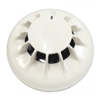
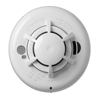
The 601PH is a high-performance optical smoke detector, part of the 600 series of plug-in detectors designed for ceiling mounting. It is certified to EN54 part 7: 2000 standard and LPCB approved, ensuring its reliability and compliance with safety regulations. This detector is engineered to react to a comprehensive range of fire products, from slow smoldering fires that produce visible particles to open flaming fires generating large numbers of very hot, smaller-sized aerosols.
A key feature of the 601PH is its combination of optical and heat technology. This innovative approach allows it to detect clear burning fire products, which historically could only be identified by ion-chamber detectors. Under normal ambient conditions, the 601PH operates as a standard optical smoke detector. However, its sensitivity significantly increases when a rapid rise in temperature is detected. In such instances, the presence of smoke confirms a fire condition, triggering an alarm.
The detector incorporates a unique "mousehole" optical chamber design, which provides an unrivaled signal-to-noise ratio. This design significantly enhances its resilience to dust and dirt, leading to reduced servicing costs. Additionally, a unique chamber cover is designed to draw slow-moving smoke into the chamber, making the detector more responsive to incipient fires.
The 601PH primarily detects visible particles generated by fires through the light scattering properties of these particles. Its optical system comprises an emitter and a receiver, with their optical axes arranged to cross within a sampling volume. The emitter projects a narrow beam of light, which baffles prevent from directly reaching the sensor. When smoke enters the sampling volume, a portion of the light is scattered, with some of it reaching the receiver. The amount of light reaching the sensor is proportional to the smoke density for a given smoke type. The amplified output from the sensor then activates an alarm circuit once a predetermined threshold is met.
The thermal measuring system is designed to detect horizontally moving hot air drafts across the ceiling, which are characteristic of fast-burning fires. This system utilizes two fast-responding negative temperature thermistors. One sensing thermistor is strategically placed above the labyrinth, under the cover, within the airstream. This allows it to detect sudden changes in air temperature or drafts of hot air moving across the ceiling. The second thermistor serves as a temperature reference; it is located outside the direct airflow but still within the smoke labyrinth and has a longer time constant. By comparing the sensing thermistor against this reference, the detector can identify significant temperature differentials. When a specific temperature differential is reached, a comparator switches, increasing the gain of the amplifier and thereby enhancing the sensitivity of the smoke sensor. Fins on top of the labyrinth are designed to increase air turbulence and improve the efficiency of the sensing thermistor.
The 601PH is designed to enhance its detection capabilities by identifying rapid temperature rises (>10°C) in air moving horizontally across the ceiling. Therefore, careful consideration should be given to its placement. It is crucial to avoid siting the sensor in positions where air is actively blown through the detector, such as near ceiling ducts, ceiling-mounted industrial heaters, or areas with forced ventilation. This ensures optimal performance and prevents false alarms or reduced sensitivity due to air currents.
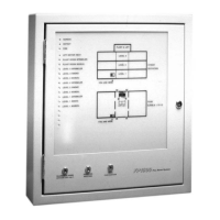
Wiring: The detector circuits require both positive and negative supply connections, which are wired to terminals L1 and L on the base (polarity insensitive). Base terminal L2 is connected to base terminal L1 when the detector is fitted, enabling continuity monitoring through the detector. Terminals L2 and L provide outputs to the next detector or End-Of-Line (EOL) device. In the event of an alarm, the detector communicates its status to the control device by sinking an additional current from the supply leads, as illustrated in Figure 3. To reset the detector from an alarm condition, power must be removed for 2-5 seconds. A drive is also provided for a remote indicator, which connects between the supply + and terminal R. If a remote indicator is used, the polarity of the supply must be known.
The service interval for each 601PH detector is dependent on the specific environment in which it is installed. However, it is generally recommended to inspect, test, and clean the detector at least annually to ensure continued optimal performance. For service replacement, the detector should typically be removed every 5 years, though this can extend up to 10 years depending on the environmental conditions.
Recycling Information: Customers are encouraged to dispose of their used equipment, including panels, detectors, sirens, and other devices, in an environmentally sound manner. Potential methods include reusing parts or entire products, and recycling components and materials. In the European Union, the Waste Electrical and Electronic Equipment (WEEE) Directive indicates that this product should not be disposed of with household waste. Instead, it should be deposited at an appropriate facility for recovery and recycling.
The manufacturer reserves the right to change the technical specifications of this product without prior notice.
| Brand | Tyco |
|---|---|
| Model | 601PH |
| Category | Smoke Alarm |
| Language | English |