Do you have a question about the Tyco IR6003/7 and is the answer not in the manual?
Describes the meaning of various LED indicators on both the Detector and the P-UIM.
Details the reset functionality for the P-UIM, both via the panel and remote input.
Guidance on selecting an unobstructed path and aligning the detector with the reflector.
Shows how to connect the detector's flying lead to a local junction box.
Illustrates input and output wiring diagrams for the P-UIM, including hazardous area configurations.
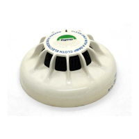
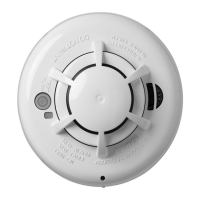
The Tyco Intelligent Oil Mist/Smoke Detector system, comprising an IR6003/x Oil Mist/Smoke Detector and a 6005/x Power Universal Interface Module (P-UIM), is engineered for the detection of oil and kerosene mists or smoke particles. This system is particularly suited for environments such as enclosed oil rig wellhead areas, generator rooms, and turbine enclosures, where the presence of such mists or smoke could indicate a hazardous condition.
The core function of the Oil Mist/Smoke Detector is to monitor the obscuration level within its beam path. It is designed to be highly sensitive to the presence of particles that would obscure the infrared beam. Upon power-up, the detector initiates an auto-calibration sequence lasting approximately 10 seconds to establish a quiescent obscuration level. During this initialisation phase, it is crucial that the beam path is clear of any obscuration to ensure accurate calibration. If the beam path is not clear, the detector may recalibrate to an unhealthy state, potentially leading to false alarms or fault conditions once the path clears. High obscuration due to dirty lenses or existing smoke/oil mist can prevent the detector from establishing an operational state, resulting in a "Clean" fault (indicated by the Clean LED pulsing ON for 4 seconds) or a "Life" fault (Life LED continuously ON). In such cases, the P-UIM will latch the fault condition, requiring both the detector and P-UIM to be reset after the beam path has been cleared and the lenses cleaned.
The detector incorporates dual automatic compensation, which allows it to adapt to gradual contamination of its lenses and more rapid environmental changes, such as temperature fluctuations. This feature helps maintain operational integrity over time. However, if lens contamination reaches a point where further deterioration cannot be tolerated, the detector will report a "CLEAN" fault, prompting the need for cleaning. If cleaning is not performed, the detector will continue to operate until a "LIFE" fault is detected, at which point it latches to an OFF condition, necessitating cleaning and a reset.
For alarm level detection, the detector continuously monitors the obscuration level. A loss of 0.5 dB in the beam path triggers a low-level alarm condition. If this loss is sustained within the 0.5 to < 1.5 dB range for a subsequent 15-second monitoring period, a low-level alarm is reported (detector LED pulses ON/OFF for 30 seconds). Should the loss exceed 1.5 dB, a high-level alarm is latched and reported. This can occur as early as 8 seconds into the alarm condition monitoring period or immediately if the high level occurs between 8 and 15 seconds. If the obscuration level drops below 0.5 dB during the monitoring period, the latched alarm is reset, and the detector resumes normal monitoring.
A "Beam Blocked" status is triggered if the obscuration level suddenly increases to a high level. If this high level is maintained for 60 seconds, the "Beam Blocked" status is reported (detector LED flashes ON for 2 seconds). If the obscuration clears for more than a few seconds within a 1-minute beam-blocked condition-monitoring period, the detector reverts to its normal operating state.
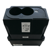
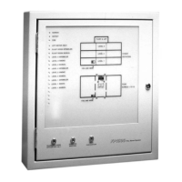
The P-UIM serves as an interface, converting the output signals from the Oil Mist/Smoke Detector into five sets of volt-free contacts. These contacts provide clear indications of the detector's status for "Fault," "Clean" (requiring lens cleaning), "Beam Blocked," "Low" Level alarm, and "High" Level Alarm conditions. The P-UIM also features a wide operating voltage range with internal voltage regulation, accepts direct input from the detector or via a barrier, and includes a remote reset feature. Local indication of both P-UIM and detector status is provided, and the module can be mounted using screws or a DIN rail.
Installation of the detector involves selecting an unobstructed path, ideally above head height, to cover the area to be monitored. The beam path should be chosen with consideration for prevailing air currents that might convey oil mist. It's important to ensure the beam is not within 500 mm of any wall or partition. The operating range of the detector is 2 to 30 metres. A reflector sheet, available in two sizes (0.6 x 0.6 metres for 2-10 metre distances and 1.2 x 1.2 metres for 10-30 metre distances), must be mounted on a flat surface and aligned horizontally and vertically with the detector. An alignment tool (Part No. 01-33-21) is recommended to ensure precise alignment of the infrared beam onto the target reflector, particularly in subdued light conditions. The reflector's design allows for up to 10 degrees of misalignment in any single plane.
For mounting the IR Detector and facilitating alignment, the 01-33-12 U-Bracket is recommended. This bracket is supplied with all necessary hardware. Electrical connection involves plugging the FLYING LEAD into the detector, ensuring the 6-way connector is aligned and the screw-locking ring is firmly tightened for weatherproofing. The free end of the cable is then wired into a local junction box, which requires a stuffing gland with a clamping range of 6 to 11 mm. Polarity is crucial: the brown wire is NEGATIVE, and the blue wire is POSITIVE. If the detector is installed in a hazardous area, an approved junction box and glands must be used, and connections must be made via an IS Isolation Safety Barrier as specified in the System Diagram SD-6003. The P-UIM can be mounted directly onto a TS35 DIN rail or screw-mounted onto a flat surface using M3 x 16 mm screws.
Commissioning involves a series of confidence checks after the detector is correctly installed and powered up. These include verifying the LED indicators (blinking on power-up, then P-UIM LIFE flashing and OUTPUT ON steady), checking for stable status after 20 seconds, blocking the beam for 1 minute to confirm "Beam Blocked" status, initiating short and long resets to verify return to normal status, and checking for a "LIFE" fault when the beam path is blocked during a long reset.
Maintenance is straightforward and involves cleaning the detector lenses and reflector every 3 months using warm water and a mild detergent, followed by drying and polishing with a clean, soft, non-abrasive cloth. After each cleaning, the system should be tested using the commissioning procedure outlined in the manual to ensure continued proper operation.
| Operating Voltage | 24 V |
|---|---|
| Quiescent Current | 25 mA |
| Alarm Current | 80 mA max. |
| Beam Length | 2 to 30 Metres |
| Dimensions | W165 x H125 x D165 mm |
|---|---|
| Weight | 0.96 kg |
| Material | Noryl GTX Grade 810 |
| Operating Temperature | -10 to +55°C |
|---|---|
| Housing Protection | IP65 |
| BASEEFA certification | Eex ib IIB T5 |
| Power Consumption | 24 V dc ±20% |
|---|---|
| Quiescent | 100 mA |
| Alarm/Fault | 130 mA |
| Detector Supply | up to 80 mA |
| Alarm Contacts | 24 V 1A (NO Volt Free) |
| Dimensions | W100 x H70 x D112 mm |
|---|---|
| Weight | 0.28 kg |
| Material | Light-grey Polycarbonate |
| Operating Temperature | 0 to +55°C |
|---|---|
| Storage Temperature | -10 to +60°C |
| Humidity | 0 to 90% RH (non-condensing) |