6. Commissioning
Once the Detector has been installed correctly by connecting it to the hazard monitoring system via the P-UIM, the user should
power up the detector loop and perform the following confidence checks
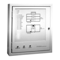
1. The Detector LED blips ON briefly as it receives power from the P-UIM. The P-UIM LIFE indicator is flashing and the OUTPUT
ON indicator is ON steady all other indicators are extinguished.
2. Wait 20 seconds and check that the status detailed in step 1 above remains unchanged.
3. Block the Detector Beam path for 1-minute and check that the detector signals a beam blocked state (LED flashes ON for
2-seconds). The P-UIM BEAM BLOCKED indicator is lit steady. Remove obstruction from the beam path.
4. Initiate a short reset and check that the P-UIM returns to the status detailed in step 1.
5. Initiate a long reset with the beam path blocked and check that Detector indicates a LIFE fault (LED is lit steady). The P-UIM
LIFE Indicator is lit steady. Remove the obstruction from the beam path.
6. Initiate a long reset and check that the P-UIM returns to the status detailed in step 1.
7. Operating Parameters
7.1 Detector
The Detector receives its dc supply from the P-UIM and provides status to the P-UIM as follows:
1. A normal/healthy detector input condition is indicated when the current is >20 mA and <32 mA (nominally 25 mA). The LED on
the front of the detector will be extinguished.
2. A low alarm condition is indicated when the current pulses from normal to 42 mA with a 1 second equal mark space ratio for a
period of 30-seconds.
3. A high alarm condition is indicated when the current pulses from normal to 42 mA with a 0.5 second equal mark space ratio for
a period of 2-minutes.
4. A beam blocked condition is indicated when the current switches from normal to 17 mA for a period of 2-seconds.
5. A cleaning fault condition is indicated when the current switches from normal to 17 mA for a period of 4-seconds.
6. A life fault condition is indicated when the current falls to 17 mA for >5-seconds.
7.2 P-UIM
The P-UIM supplies the detector circuit and monitors the current in the detector loop to determine the detector status as follows:
1. An open circuit condition is detected if the current is <6.3 mA for >2 seconds. 2. A normal/healthy detector input condition is
when the current is >20 mA and <28 mA.
3. A low alarm condition is detected when the current pulses from normal to >28 mA and <42 mA with a 1 second equal mark
space ratio for a period of 5 seconds.
4. A high alarm condition is detected when the current pulses from normal to >28 mA and <42 mA with a 0.5 second equal mark
space ratio for a period of 5 seconds.
5. A beam-blocked condition is detected when the current switches from normal to <16 mA for a period of 2 seconds. The fault
detection-monitoring period is 5 seconds from the receipt of the fault state.
6. A cleaning fault condition is detected when the current switches from normal to <16 mA for a period of 4 seconds. The fault
detection-monitoring period is 5
Seconds from the receipt of the fault state.
7. A life fault condition is detected when the current falls to <16 mA for >5 seconds. The fault detection-monitoring period is 5
seconds from the receipt of the fault state.
8. A short circuit condition is detected if the current increases to >74 mA for >5 seconds. The fault detection-monitoring period is 5
seconds from the receipt of the fault state. Power is removed from the detector
Note:
When the alarm or fault condition has been rectified the P-UIM and Detector should be reset.
11 / 12
 Loading...