5. Installation
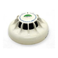
5.3 Detector Connection Details
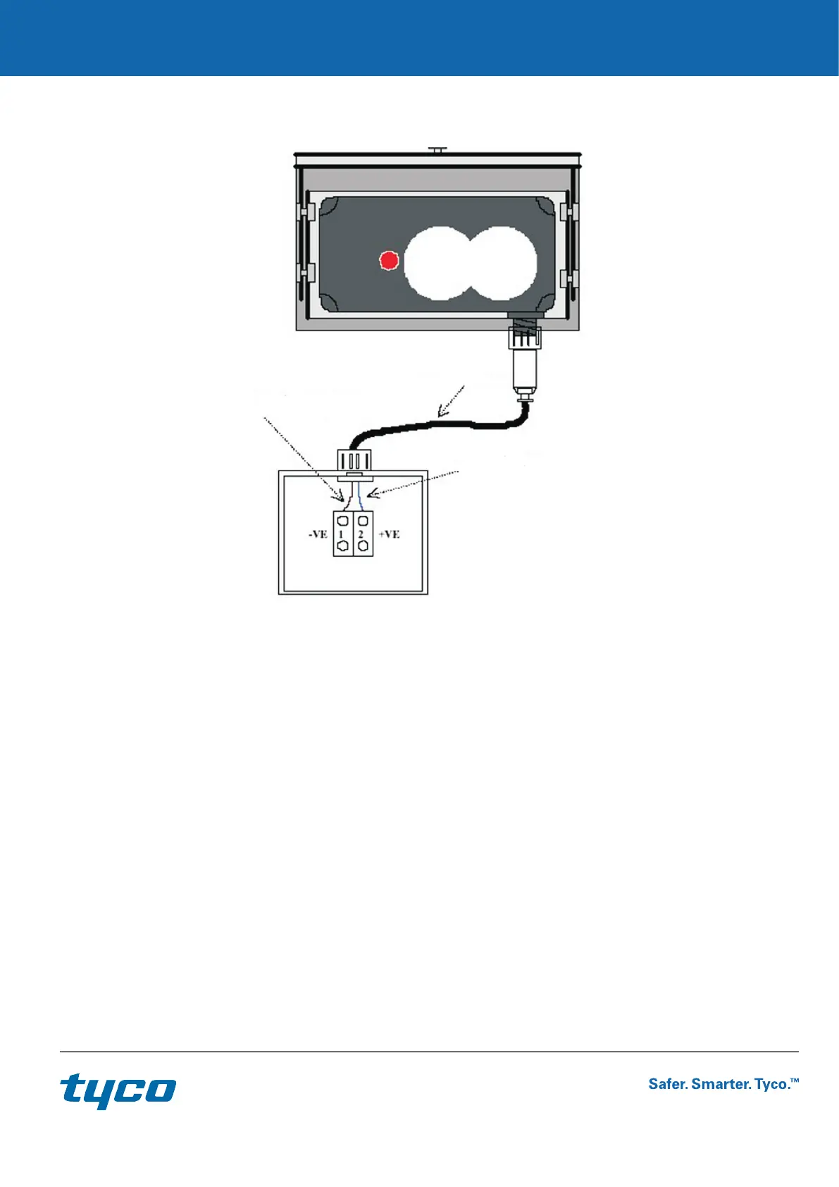
Negative - Wire No 1
Colour - Brown
01-33-14 Flying Lead
Positive - Wire
Colour - Blue
Local Junction Box
The diagram above shows the detector connected to a local junction box via the flying lead (Part No. 01-33-14). The local junction
box will require connecting to the P-UIM, which provides the necessary Detector to user equipment interface.
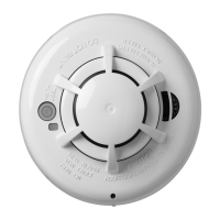
5.4 Flying Lead Connections
When the detector has been mounted the FLYING LEAD can be plugged into the detector. Align the 6-way connector and insert.
Firmly tighten the screw-locking ring to ensure weatherproofing.
The free end of the cable can now be wired into a local junction box as shown above. Entry into the junction box requires a stuffing
gland with a clamping range of 6 to 11 mm.
Please note the wire colour vs polarity, Brown is NEGATIVE, Blue is POSITIVE.
Warning
If the detector is mounted in a hazardous area then an approved junction box and glands must be used. Connections must be via a
IS Isolation Safety Barrier as specified in the System Diagram SD-6003.
7 / 12
 Loading...