EasyManua.ls Logo

Tyco FP1600 - User Manual

Tyco FP1600
30 pages
Print Icon
To Next Page IconTo Next Page
Loading...
LT0312
FP1600 / OMEGA 64
INSTALLATION AND
CONFIGURATION MANUAL
Site Name:
This manual should be left in the panel
Question and Answer IconNeed help?

Do you have a question about the Tyco FP1600 and is the answer not in the manual?

Summary

Safety and Warnings

General Safety Warnings

Important requirements for installation, commissioning, and testing of fire alarm systems.

Operating Instructions

Display Codes Reference

System States and Alarms

Defines codes for system states, alarms, isolates, and common defects displayed on the panel.

Programming Menu Guide

Entering and Saving Programming

Details the procedure to enter, navigate, and save changes in programming mode.

Programming Options and Codes

Zone Programming and Mapping Codes

Lists codes and options for zone types, and mapping to ancillaries, groups, and variables.

Programming Flowchart

Zone Programming Flowchart

Visual guide for programming zone types, mapping, and options using buttons.

Group and Ancillary Flowchart

Flowchart illustrating the programming sequence for groups and ancillaries.

Master Board Configuration Tables

Zone Configuration and Mapping

Tables for configuring zone types, mapping, and notes for master board zones 1-16.

2 nd Board Configuration Tables

Zone Configuration and Mapping (2 nd Board)

Tables for configuring zone types and mapping for zones 17-32 on the 2nd board.

3 rd Board Configuration Tables

Zone Configuration and Mapping (3 rd Board)

Tables for configuring zone types and mapping for zones 33-48 on the 3rd board.

4 th Board Configuration Tables

Zone Configuration and Mapping (4 th Board)

Tables for configuring zone types and mapping for zones 49-64 on the 4th board.

5 th Board Configuration Tables

Zone Configuration and Mapping (5 th Board)

Tables for configuring zone types and mapping for zones 65-80 on the 5th board.

6 th Board Configuration Tables

Zone Configuration and Mapping (6 th Board)

Tables for configuring zone types and mapping for zones 81-96 on the 6th board.

Overview

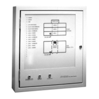
The FP1600 / OMEGA 64 is a 16-zone self-contained conventional fire alarm system, designed to be expandable in multiples of 16 zones up to a maximum of 96 zones. It is specifically engineered to meet NZS 4512:1997, the New Zealand Building Code (Section F7), and the NZ Fire Service requirements for connection to remote receiving stations.

Function Description:

The system serves as a fire alarm control panel, monitoring various types of zone circuits and initiating alarms or defects based on detected conditions. It offers extensive configuration options to tailor its operation to specific site requirements.

Important Technical Specifications:

  • Zone Capacity: 16 zones (base unit), expandable to 96 zones.
  • End of Line Resistor: All circuit types use a 2k70, 1% End of Line Resistor.
  • Battery Charger: Constant voltage and current-limited (13.65V, 2A nominal), temperature-compensated for a 12V sealed lead-acid battery. Multiple chargers can operate in parallel.
  • Ancillary Relay (Ar): 30V, 5A max (Resistive) single pole changeover relay.
  • On-Board Ancillary Outputs (A20-, A21-): Two hard-wire open collector output tabs.
  • Additional Relay/Ancillary Outputs: 19 ancillary outputs via a 26 Way Flat Ribbon Cable (J21) and a Mimic Termination Board (PA0702). All are 30V, 200mA open collector drivers (except LAMP-).
  • Bells Output: Maximum total load is 5A (subject to battery/charger capacity limitations). Supervision is programmable. Series diodes (e.g., 1N4004) and EOL resistors (1 Branch: 9k1 1% EOL, 2 Branches: 2 x 18k 1% EOLs, or 3 Branches: 3 x 27k 1% EOLs) are required for all alerting devices.
  • RZDU Interface: Supports up to 8 compatible Remote Zone Display devices with a 3 or 4-core star-spur wiring arrangement.
  • Mains Switch: Provides 230V Mains isolation.
  • Earth Fault Monitoring: Detects leakage from field wiring to earth; can be disabled by cutting link R65 on Mk3 boards.

Usage Features:

  • Flexible Programming: Offers extensive programming facilities to define system operation.
  • Keypad Circuit Isolation: Provides isolation for the keypad circuit.
  • Six Zone Circuit Types:
    • Flowswitch: Instant alarm on open circuit, defect on short circuit. Non-latching, non-Brigade signalling, non-Bell ringing by default. Programmable delay (0-25 seconds, default 5 seconds) before alarm activation.
    • Thermal: Instant alarm on open circuit, defect on short circuit. Latching, Brigade signalling, and Bell Ringing by default.
    • Evacuation Control: Supervised connection to a sprinkler DBA “Bell” output (Master board zones 1-16 only). Instant alarm on short circuit, defect on open circuit. Non-Latching, Non-Brigade signalling, and Bell ringing by default. Unaffected by Silence Alarms switches.
    • Combined: Connects conventional 2-wire smoke detectors and clean contact devices. Instant alarm on open circuit, defect on short circuit. Latching, Brigade signalling, Bell ringing, and smoke detector AVF enabled by default.
    • Smoke: Connects conventional 2-wire smoke detectors and clean contact devices. Defect on open circuit. Instant alarm on short circuit if "MCP" facility is used (requires PA0443 Contact conversion module for N/C contacts). Latching, Brigade signalling, Bell ringing, smoke detector AVF enabled, and "MCP" option disabled by default.
    • Residential: Connects conventional 2-wire smoke detectors and clean contact devices. Defect on open circuit. Instant alarm on short circuit if "MCP" facility is used (requires PA0443). "MCP" option disabled, smoke detectors non-Brigade signalling, non-Bell ringing, non-Indicating, AVF enabled by default. Latching for smoke detector activation for a per-board programmable period (0-250 sec, default 30 sec, 0 = stay latched) before self-reset attempt.
    • Disabled: Shuts down circuits to save current; EOL resistor optional.
  • Automated Self-Test: Performs internal RAM/EEPROM checksum tests and exercises all zone circuits. An automatic version runs daily during the charger inhibit period.
  • History Log: Stores the 15 most recent significant events per board in chronological order (RAM-based, lost on power failure).
  • 7-Segment Displays: Three displays per board for status and codes.
  • Zone Index LEDs: Single flash for thermal/manual alarm, double flash for smoke alarm. Normal LED has a power-save cadence when mains is off.
  • Buzzer: Indicates abnormal conditions or defects.
  • Evacuation Switch: Manually activates alerting devices without calling the Brigade; can activate ancillary outputs.
  • Silence Alarms Switch: Prevents alerting devices from sounding; can de-activate ancillary outputs. Does not silence Evacuation Control circuit alarms or ERD- input.
  • Services Restore Switch: Allows Brigade to restore ancillary services during an alarm; programmable effect on ancillary outputs.
  • Brigade Interface: Requires a 2W/4W General Purpose SGD (PA0862) or General Purpose Brigade Relay Interface (PA0861) for connection to remote receiving stations.
  • RZDU Interface: Up to 8 Remote Zone Display devices can be connected, providing Brigade control switches and a Brigade index.
  • Control Buttons (Internal): Four pushbuttons for accessing current/latched display info, operator functions, and programming. Includes "Current Defects," "Latched Defects," "System Status," and "Function" menus.
  • Panel Reset: Clears latched conditions, modes, and indications.
  • Lamp Test: Initiates a test of all lamps.
  • Non-Latching Test (NLT) Mode: Temporarily sets all enabled zone circuits to indicating, non-latching, bell-ringing, non-brigade calling, with no delays or gating.
  • Zone Isolation: Individual zone isolation/de-isolation (toggle function) available on a board-by-board basis.
  • Charger Inhibit: Starts a 40-minute period of reduced voltage charging, also initiates an automatic self-test.
  • Ancillary Output Programming: Ancillary outputs follow a logical OR of selected options, with overrides for standards (e.g., Evacuation overrides Silence Alarms).
  • Programming Groups: Groups exist within a board, active when all mapped zones on that board are in alarm and not isolated. Can be latching and mapped to ancillary outputs or universal variables.
  • Universal Variables: 16 programmable variables (U01-U16) accessible by all boards, allowing logical OR combinations of zone/group statuses. Can be mapped to ancillary outputs.
  • Ancillary Override: If enabled, "Door Open" is treated like operating the Services Restore switch.
  • Defect Buzzer Cancel Input (DBC-): Momentary closure to 0V silences the local mode defect buzzer (Master board only).
  • External Defect Input (Ext DEF-): Pulling to 0V generates a defect.
  • External Reset Input (Ext RST-): Pulling to 0V generates a Panel Reset (Master board only).
  • Evacuation Relay Drive Input (ERD-): Pulling to 0V activates alerting devices (non-silencable) (Master board only). Not implemented in V4.00 software.

Maintenance Features:

  • Programming Mode: Accessed by pressing and holding all three Master board "Program" buttons. Requires "Data Program Enable" link for saving changes.
  • Self-Test Failure Codes: Displays specific codes for self-test failures.
  • Door Switch Supervision: (Master board only) Requires a 220kΩ 1% resistor across Services Restore switch terminals for Mk3 Master boards in older cabinets.

Tyco FP1600 Specifications

General IconGeneral
BrandTyco
ModelFP1600
CategorySmoke Alarm
LanguageEnglish

Related product manuals