801AP
17A-05-AP
4 8/07
© 2007 Tyco Safety Products PAGE 5 of 10
EQUIPMENT:
PUBLICATION:
ISSUE No. & DATE:
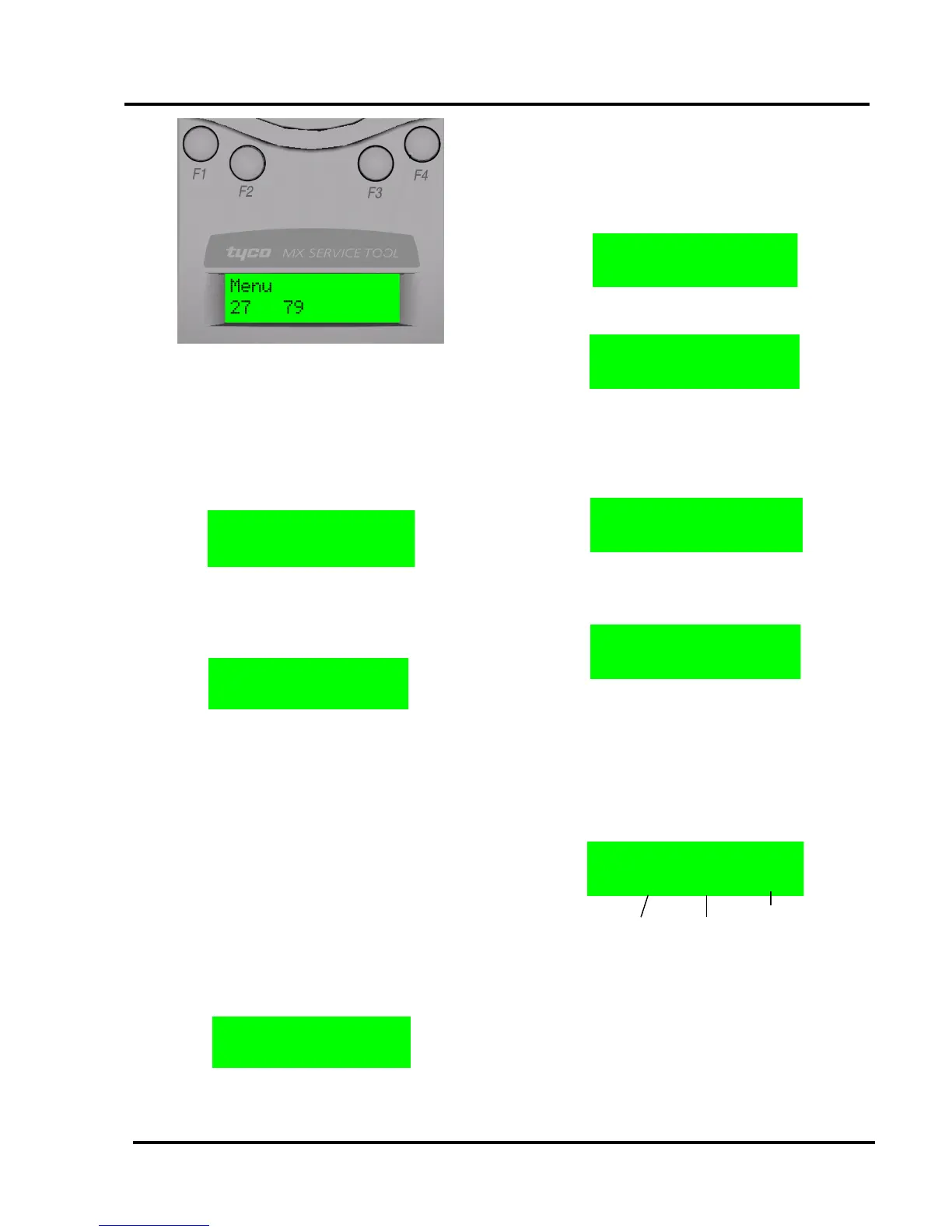
In Fig. 8 pressing F1 selects the ‘Menu’, F2-F4 are redundant
here.
3.5 FUNCTIONALITY
ADDRESS PROGRAM
The main menu starts with ADDRESS PROGRAM. Press
buttons F2 or F3 to choose ‘Select’ and the address of the
device is displayed
(eg, address 4).
• Use ‘Write’ to program the device with a new
address
• ‘Menu’ to return to the main menu
• ClU to clear the memory map of used
addresses
Note: Whenever ‘Menu’ appears on the display, this
always returns to the main menu.
The Service Tool saves a memory map of the addresses that
have been programmed. To erase this, select menu and
choose Clear Used ‘ClU’.
If ‘Write’ is selected, the following screen is displayed:
• Use ‘Up’ to increase the address number
• ‘Dn’ to decrease it
• ‘Write’ to program the address displayed
• ‘Back’ to return to the previous screen
If ‘Write’ is selected then the following message will appear
for 2 seconds:
This is followed by:
Having programmed an address, the Service Tool moves to
the next sequential unused address.
If an address has already been used, the Service Tool
indicates:
If the user then decides to use a previously used address, the
following screen is displayed:
Press ‘Write’ and the Service Tool displays
‘PROGRAMMED OK’ briefly and then displays the next
available sequential address.
ANALOGUE VALUES
ANALOGUE VALUES displays the analogue values of the
attached device.
The above example shows a device with 2 channels, eg, an
Optical/Heat detector, where channel 1 is the optical value
and channel 2 is the heat value. Press ‘Menu’ to return to the
main menu.
Note:
1) Only displayed if channel 3 is used on a device.
2) These are the values that the device would
transmit to the control panel. The values do
NOT
include any calibration or correction factors.
Back Write Dn Up
PROGRAMMED OK