TFP802
Page 2 of 6
Technical
Data
Approvals
The natural finish, chrome plated, and
lead coated bronze, as well as stain-
less steel Type D3 PROTECTOSPRAY
Nozzles are UL and C-UL Listed, as
well as FM and EAC Approved.
Maximum Working Pressure
175 psi (12,1 bar)
Also refer to Figure 2, Note 2
Discharge Coefficient
Refer to Table A
Spray Angles
Refer to Table B
Finish and Material
Refer to Table E
Thread Connection
1/2 inch NPT
Physical Characteristics
(Bronze)
Frame . . . . . . . . . . . . . . . . . . . . . . . . . . . .Bronze
Deflector . . . . . . . . . . . . . . . . . . . . . . . . . .Bronze
Splitter . . . . . . . . . . . . . . . . . . . . . . . . . . . .Bronze
Pin . . . . . . . . . . . . . . . . . . . . . . . . . . . . . . .Bronze
Physical Characteristics
(Stainless Steel)
Frame ............ASTM A-743 Grade CF-8M
(equiv. Type 316 S.S.)
Deflector . . . . . . . . . . . . . . . . . . . . Type 316 S.S.
Splitter . . . . . . . . . . . . . . . . . . . . . . Type 316 S.S.
Pin ......................... Type 316 S.S.
Design
Criteria
Nozzle Placement. Where direct
impingement of water spray onto all
of the protected surface is required by
the authority having jurisdiction, the
nozzles are to be spaced and directed
so that their spray patterns will com-
pletely cover the plane-of-protection
with the minimum required average
density; however, it is recommended
that indoor nozzle spacing be 12 ft.
(3,7 m) or less and that outdoor nozzle
spacing be 10 ft. (3,0 m) or less. Where
rundown or slippage is planned, such
as, exposure protection of vessels per
NFPA 15, the above rec ommended
indoor and outdoor spac ings also
apply.
When used for protecting the surfaces
of a vessel, for example, the nozzles
are positioned normal to and approxi-
mately 2 ft. (0,6 m) from the surface.
This approach, in conjunction with
a properly selected spray angle, will
tend to make more effective use of the
spray as well as help minimize the dis-
turbance effects of wind/draft condi-
tions on the water spray patterns.
Spray Patterns. The Design Spray
Profiles for the nozzle spray angles of
65 to 180 degrees are shown in Figure
2 and apply to discharge pressures of
20 to 60 psi (1,4 to 4,1 bar). Discharge
pressures in excess of 60 psi (4,1 bar)
will result in a decrease in coverage
area since the spray patterns tend to
draw inwards at higher pressures. Refer
inquiries on higher discharge pressures
to the Technical Services Department.
The maximum axial distances between
the nozzle tip and plane-of-protection,
for exposure protection, are given in
Table C and D. When the axial dis-
tance from the nozzle tip to the plane-
of-protection is 2 ft. (0,6 m) or less,
the Design Spray Profile is the same
as the nominal spray angles of 65 thru
140 degrees.
Main Pipeline Strainers. Main pipe-
line strainers per NFPA 15 are required
for systems utilizing nozzles with a flow
path less than 3/8 in. (9,5 mm) diam-
eter, i.e., No. 16 thru No. 24 (Ref. Table
A), and for any system where the water
is likely to contain obstructive material.
Installation
The TYCO Type D3 Protectospray
Nozzles must be installed in accor-
dance with this section.
General Instructions
A leak-tight 1/2 inch NPT nozzle joint
should be obtained by applying a
minimum to maximum torque of 7 to 14
ft.-lbs. (9,5 to 19,0 Nm). Higher levels
of torque may cause impairment of the
nozzle.
Step 1. With pipe-thread sealant
applied to the pipe threads, hand
tighten the nozzle into the nozzle fitting.
Step 2. Tighten the nozzle into the
nozzle fitting using only the W-Type 11
Sprinkler Wrench (Figure 3). With ref-
erence to Figure 1, apply the W-Type
11 Sprinkler Wrench to the wrenching
area.
ORIFICE
SIZE
MINIMUM
DIAMETER
K-FACTOR
GPM/psi
½
LPM/bar
½
NO. 16 0.203” (5,16 mm) 1.2 17, 3
NO. 18 0.250” (6,35 mm) 1.8 25,9
NO. 21 0. 281” ( 7,14 m m ) 2.3 33,1
NO. 24 0.328” (8,33 mm) 3.0 43,2
NO. 28 0.375” (9,53 mm) 4.1 59,0
NO. 32 0.438” (11,13 mm) 5.6 80,6
NO. 34 0.500” (12,70 mm) 7. 2 103,7
65° 80° 95° 110° 125° 140° 160° 180°
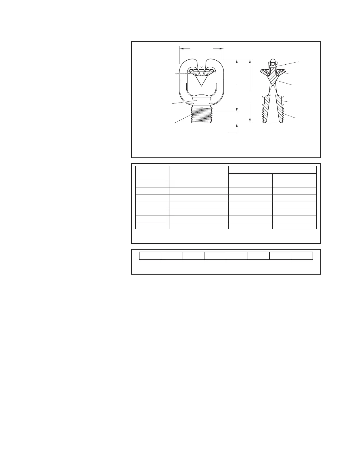
AREA
2-1/2"
(63,5 mm)
(44,5 mm)
2-1/16"
(52,4 mm)
1/2" NPT
ORIFICE SIZE
STAMPED ON
WRENCHING
AREA
PIN
DEFLECTOR
SPLITTER
FRAME
7/16" (11,1 mm)
SPRAY ANGLE
OF DISCHARGE)
STAMPED ON
DEFLECTOR
FIGURE 1
TYPE D3 PROTECTOSPRAY NOZZLES
NOMINAL DIMENSIONS
TABLE A
SELECTION OF ORIFICE SIZES
TABLE B
SELECTION OF SPRAY ANGLES
 Loading...