TFP802
Page 3 of 6
Care must be exercised to avoid
damage to the nozzles before, during,
and after installation. Nozzles damaged
by dropping, striking, wrench twist/slip-
page, or the like, must be replaced.
Frequent visual inspections are rec-
ommended to be initially performed
for nozzles installed in potentially cor-
rosive atmospheres to verify the integ-
rity of the materials of construction and
finish as they may be affected by the
corrosive conditions present for a given
installation. Thereafter, annual inspec-
tions per NFPA 25 are required.
Water spray fixed systems for fire pro-
tection service require regularly sched-
uled care and maintenance by trained
personnel. In addition to inspect-
ing nozzles for proper spray perfor-
mance during water flow trip tests of
the system, it is recommended that
nozzles be periodically inspected
for broken or missing parts (includ-
ing blow-off plugs where applicable),
loading/obstructions, or other evidence
of impaired protection. The inspec-
tions should be scheduled weekly or
as frequently as may be necessary,
and corrective action must be taken
to ensure that the nozzles will perform
as intended in the event of a fire.
For installations subject to freezing
and where blow-off plugs have been
installed, a periodic inspection must be
performed for evidence of ice build-up
from trapped condensate which could
affect the proper release of the blow-
off plugs.
The owner is responsible for the inspec-
tion, testing, and maintenance of their
fire protection system and devices in
compliance with this document, as well
as with the applicable standards of the
NATIONAL FIRE PROTECTION ASSO-
CIATION (e.g., NFPA 25), in addition to
the standards of any other authorities
having jurisdiction. Contact the install-
ing contractor or product manufacturer
with any questions.
Water spray fixed systems are rec-
ommended to be inspected, tested,
and maintained by a qualified Inspec-
tion Service in accordance with local
requirements and/or national codes.
Care and
Maintenance
The TYCO
Type D3 PROTECTOSPRAY
Nozzles must be maintained and ser-
viced in accordance with this section.
Before closing a fire protection system
main control valve for maintenance
work on the fire protection system that
it controls, permission to shut down the
affected fire protection system must be
obtained from the proper authorities
and all personnel who may be affected
by this action must be notified.
Type D3 PROTECTOSPRAY Nozzles
must never be painted, plated, coated
or altered in any way after leaving the
factory; otherwise, the spray perfor-
mance may be impaired.
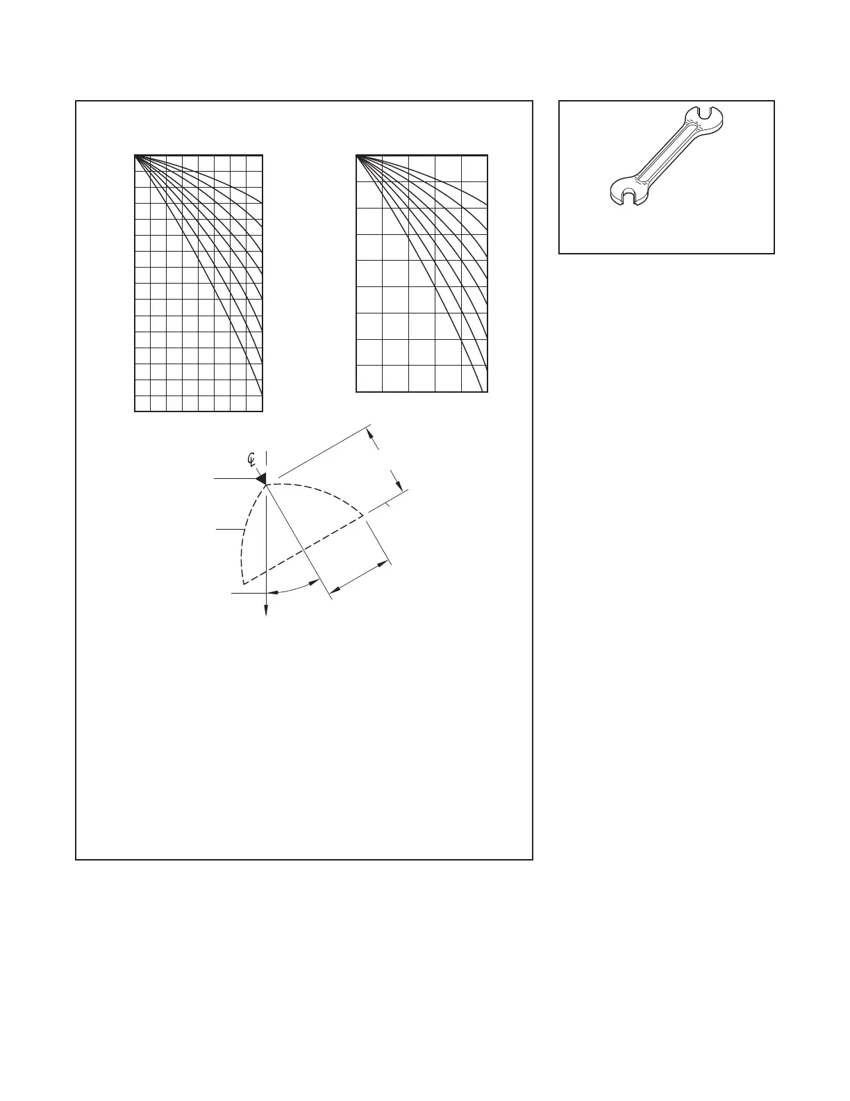
AXIAL DISTANCE
NOZZLE
PLANE OF
PROTECTION
PROFILE
SPRAY
(ORIENTATION)
FIXED ANGLE
GRAVITY
The shapes of the Design Spray Proles remain essentially unchanged over the
maximum Axial Distances shown in Tables C and D.
Refer to the authority having jurisdiction for their minimum required residual pressures.
3.
Design data applies to a residual (owing) pressure range at the nozzle inlet of 20 to
60 psi (1,4 to 4,1 bar). For pressures up to 175 psi (12,1 bar) consult Johnson
Controls Technical Services.
Design data obtained from tests in still air.
2.
1.
DISTANCE
RADIAL
For axial distances of 2 feet (0,6 meters) and less and for nozzle spray angles of 65°
to 140°, the Design Spray Prole is the same as the nominal spray angle.
4.
The maximum Axial Distances shown in Tables C and D are based on exposure
5.
95°
65°
80°
0
14
12
10
8
6
4
2
0
2 4 6 8
NOZZLE CENTERLINE, FEET
AXIAL DISTANCE FROM NOZZLE, FEET
80°
95°
0,5
0
1,0
1,5
2,0
2,5
3,0
3,5
4,0
4,5
0 0,5 1,0 1,5 2,0 2,5
NOZZLE CENTERLINE, METERS
RADIAL DISTANCE FROM
AXIAL DISTANCE FROM NOZZLE, METERS
FIGURE 2
WATER DISTRIBUTION DESIGN DATA
FIGURE 3
W-T YP E 11
SPRINKLER WRENCH
 Loading...