12
2.1 C24 Communications Enrollment
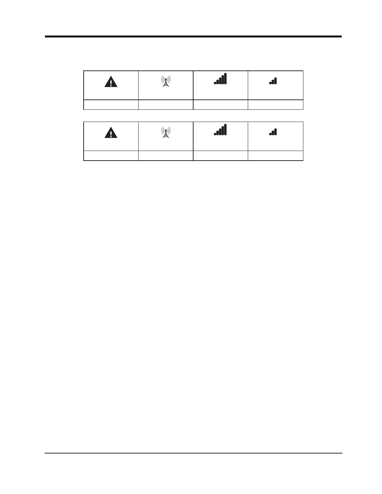
When the 3G4010/LE4010 sends a request to communicate to the next central station, the bottom signal
strength LED begins flashing and turns on solid when it receives a communication back from the central sta-
tion.
Red Blue
Yellow/Green
(Top)
Yellow/Green
(Bottom)
ON ON ON FLASHING
and turns on solid when it receives a communication back from the central station.
Red Blue
Yellow/Green
(Top)
Yellow/Green
(Bottom)
ON ON ON ON
If at least one of the central stations does not respond back to the communicator, the signal strength LED cor-
responding to that central station turns off. Once the initialization sequence is complete, the 3G4010/LE4010
switches to steady state operation.
Step 6 - Mount the 3G4010/LE4010
1. Power down the 3G4010/LE4010 by removing the DC power source and battery leads.
2. Using the cabinet, mark the four screw locations. Drill the anchor screw holes.
Note: Check for cable conduits and water pipes before drilling.
3. Using anchor screws (not provided), mount the cabinet to the wall.
4. Run the cables through the cable entry [13] or through the cabinet knockouts.
5. Complete the connections on the terminal blocks [11].
Note: Ensure that power and Telco circuit connections are made only after the cabinet has been secured to the
building or structure, and has been connected to the protective earth ground. Descriptions of the terminals can
be found in the ‘Connecting the 3G4010/LE4010’ section.
6. Reattach the front cover [1] securely to the cabinet.
Note: Please refer to the end of this manual for wiring diagrams.
 Loading...