5
41
2
3 6
7 8 9
10
11
14
15 16
17
LE
LI
O1O2 O3 O4
+OC
13
12
AS
L1
L2
L3
L4
1K5
T
I
P
R
I
N
G
32
DC INAUX
2 31
COM
41
COMT1 R1TIPRING
4
PGM ZONE
+
-
RJ-45
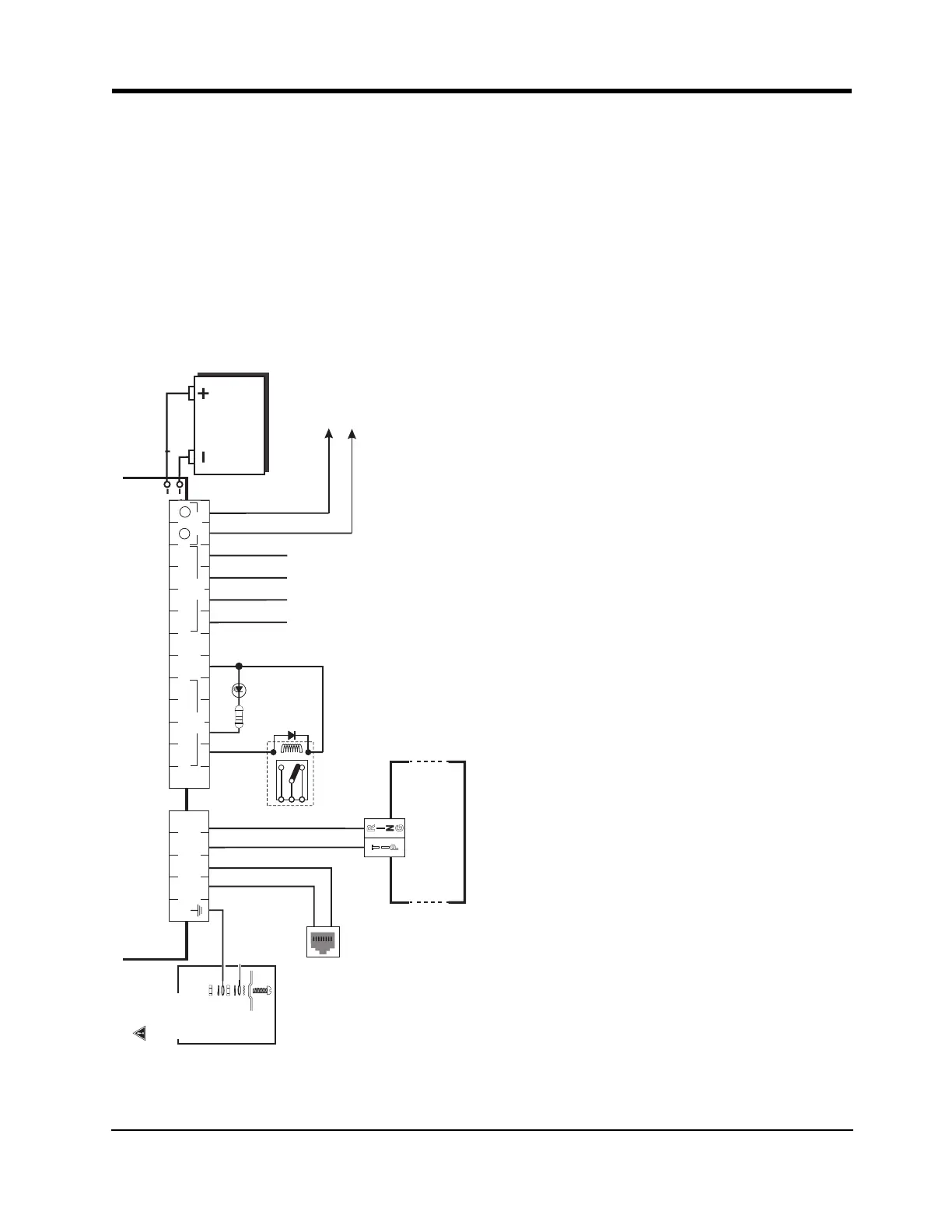
BATTERY
Sealed Rechargeable
12V / 1.2Ah
Typical battery charge: 30-50 mA
Recommended Model: 12V/1.2Ah
Battery not required
if CON5 is set to NO BAT
9-14VDC/ 700mA (max)
Earth-ground
Ground wire from
building electrical
installation
Inputs to be connected
to dry contact outputs
from alarm control panel
with 5.6KΩ EOL resistors
}
GROUND
CONNECTION
Tighten nut to break paint &
make good connection to
the cabinet.
Nut
Nut
Bolt
Lock washer
Lock washer
Star washer
Cabinet
Alarm Control Panel with
Dialler Interface
(Supports Contact ID and
SIA formats)
Panel Aux Power or
External Power Supply
Telephone Line
Connection
Supervision
Relay
RM1-UL Installations
RM1C-ULC Installations
Connect relay contacts to
a zone input on the alarm
control panel for communicator
troubles supervision
(24hr-type zone)
Optional
use of PGM
output (See
Programming)
WARNING!
HIGH VOLTAGE. DISCONNECT AC
POWER & TELEPHONE LINES
PRIOR TO SERVICING
WARNING: Incorrect connections may result in PTC failure or improper operation. Inspect wiring and ensure connections are correct before turning on.
All circuits are classified for UL installations as Power Limited/Class II Power Limited except for the battery leads which are not Power Limited. Do not route any wiring over circuit
boards. Maintain at least 1” (25.4mm) separation. A minimum 1/4” (6.4mm) separation must be maintained at all points between Power Limited wiring and all other Non-Power
Limited wiring. Route wires as indicated in the diagram.
For UL Installations, the system shall be installed in accordance with chapter 2 of the ANSI/NFPA 72 and ANSI/NFPA70. Recommended locations and wiring methods shall be in
accordance with the National Electrical Code, ANSI/NFPA 70, the Standard for Installation and Classification of Burglar and Holdup Alarm Systems, UL 681, and the Standard for
Central-Station Alarm Services, UL 827.
For ULC Installations, the recommended locations and wiring methods shall be in accordance with CSA C22.1, Canadian Electrical Code, Part I, Safety Standard for Electrical Installa-
tions; CAN/ULC-S302, Installation and Classification of Burglar Alarm Systems for Financial and Commercial Premises, Safes and Vaults; and CAN/ULC-S301, Standard for Central and
Monitoring Station Burglar Alarm Systems and the Standard for the Installation of Residential Fire Warning Systems, CAN/ULC-S540. Do not install the equipment in places where the
signal strength does not meet the minium recommended signal strength level. Do not run zone inputs and T1/R1 wiring along AC wires or other circuits with high frequency signals
in order to reduce possibility of interference and false alarms.
(Use No. 26 AWG wires for
the connection to PSTN)
For ULC Fire Monitoring installations fire alarm signals shall be sent
simultaneously over POTS line (using the dialler) and over the
wireless network (using 3G4010/LE4010). Connect alarm output
from control panel (PGM) to the input on the communicator that is
programmed as a Fire Alarm Input.
Examples of Control Units/Subscribers Units or Power Supplies
compatible models: DSC PC1864, PC1832, PC1616, PC5204, etc.
This connection
is necessary
 Loading...