32
32
DC INAUX
2 31
COM
41
COMT1 R1TIP RING
4
PGM ZONE
+
-
5.6 KOhm
5.6 KOhm
Cellular
Network
Supervision
Relay
Phone Line
Supervision
Relay
Redundant
Fire Alarm
Initiation
3G4010
AC AC RED BLK YEL GRN Z1 COM Z2 Z3 COM Z4 Z5 COM Z6 Z7 COM Z8
AUX+ BELL+
AUX- BELL-
PGM1 PGM3
EGND
TIP T-1
PGM2 PGM4
RING R-1
PC1864
Only
PC1864
PC1832
Only
AC AC RED BLK YEL GRN Z1 COM Z2 Z3 COM Z4 Z5 COM Z6 Z7 COM Z8
AUX+ BELL+
AUX- BELL-
PGM1 PGM3
EGND
TIP T-1
PGM2 PGM4
RING R-1
PC1864
Only
PC1864
PC1832
Only
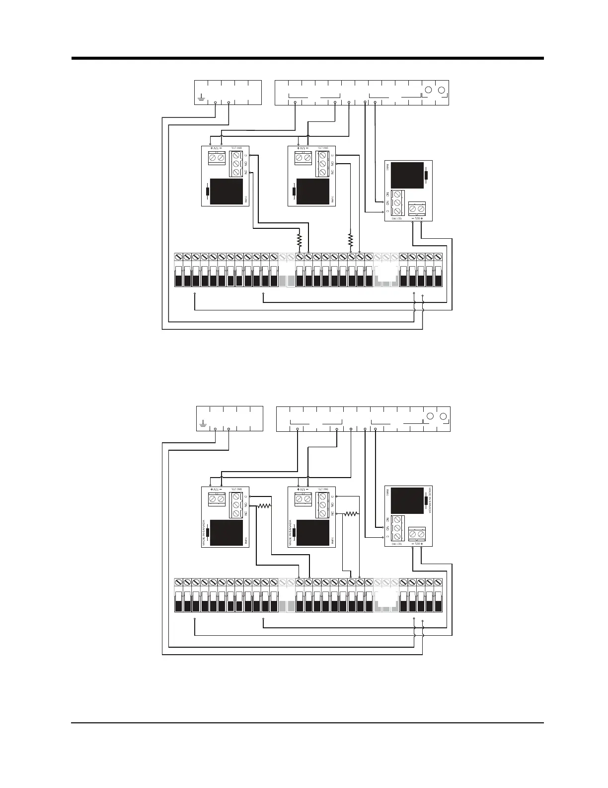
Note: Use EOL resistor in series with N.O. contacts of the relay connected to PGM4.
Figure 12-10 Connection Details for Cellular Network Supervision Relay, Phone Line Supercision Relay and
Redundant Fire Alarm Transmission
5.6 KΩ
5.6 KΩ
Cellular
Network
Supervision
Relay
Phone Line
Supervision
Relay
Redundant
Fire Alarm
Initiation
3G4010
AC AC RED BLK YEL GRN Z1 COM Z2 Z3 COM Z4 Z5 COM Z6 Z7 COM Z8
AUX+ BELL+
AUX- BELL-
PGM1 PGM3
EGND
TIP T-1
PGM2 PGM4
RING R-1
PC1864
Only
PC1864
PC1832
Only
AC AC RED BLK YEL GRN Z1 COM Z2 Z3 COM Z4 Z5 COM Z6 Z7 COM Z8
AUX+ BELL+
AUX- BELL-
PGM1 PGM3
EGND
TIP T-1
PGM2 PGM4
RING R-1
PC1864
Only
PC1864
PC1832
Only
21
COMT1 R1TIP RING
3
DC INAUX
2 31
COM
4
4
PGM ZONE
+
-
Note: Use EOL resistor in parallel with N.O. contacts of the relay connected to PGM4.
3G4010/LE4010 Installation Manual
 Loading...