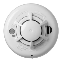
PG9936H Wireless Heat Detector
Installation and Operating Instructions
Read this instruction sheet thoroughly before installation and use of the PG9936H
Introduction
The PG9936H is a wireless heat detector with a fixed temperature and rate of rise heat sensor
and an internal piezoelectric alarm.
The following versions are available:
Frequency (MHz) Version Region
915 PG9936H Middle East
Compatible Devices
This detector is compatible with UL Listed IQPanel2 Wireless Control Panels using PowerG
Technology.
For UL installations use this device only in conjunction with
compatible IQPanel2 wireless receivers. Transmissions occur
at approximately 915 MHz (912MHz to 919 MHz).
Operation
During normal operation, the green LED flashes every 60 seconds.
The detector goes into alarm when the heat level exceeds 135 ºF / 58 ºC and automatically
restores when the heat level falls below the threshold. The detector also goes into alarm when
the temperature rapidly increases over a short period of time. During an alarm, the LED flashes
once per second and the sounder emits the fire evacuation temporal 3 pattern.
Detector Trouble
If the detector has a general fault, the yellow LED blinks once every four seconds and emits a
chirp every 48 seconds. After four hours, the panel displays a fire trouble message.
Detector and Status Indication
Status LEDs
Sounder
Normal Double Green flash every 60 seconds Off
Heat Alarm Red flash every 1 second ANSI S3.41 temporal 3
Heat Test Red flash every 1 second ANSI S3.41 temporal 3
Test Alarm
(button
press)
Red flash every 1 second ANSI S3.41 temporal 3
Detector
Trouble
Yellow flash every 4 seconds One chirp every 48 seconds
Low Battery Yellow flash every 12 seconds
One chirp every 48 seconds
(press button to hush for 12 hours)
Power-up Red, yellow, green, flash sequence
One chirp at the end of the power-up
sequence
Tamper
Red, yellow, green flash sequence every
12 seconds
Off
Tamper
Removing the detector from the mounting plate initiates a “tamper” transmission. The tamper
condition is restored after the detector is mounted on the plate.
Wireless Transmissions
A supervisory message is transmitted at 128 second intervals. If the signal is not received, the
control panel determines that the detector is missing.
The detector transmits the following:
l
Alarm / Alarm Restore -Transmitted at time of occurrence.
NOTE: During an alarm condition, the detector sends an alarm event to the control panel.
When the condition is restored, the detector sends an alarm restore event to the
panel and sets the alarm restore indicator. The red LED blinks once every four